CASE STUDIES · Smart Locks & Door Hardware
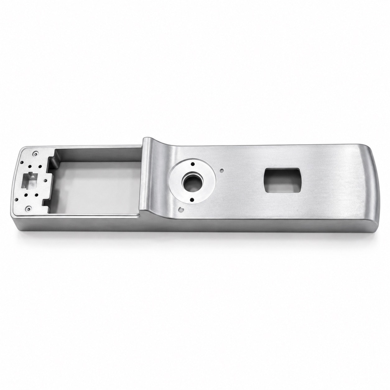
Zinc Die-Cast Smart Door Lock Front Panel: Plating Blisters Cut From About 8% to Under 0.5%
Plating blistered and flow marks marred the show face. Gates sized to each region and knit lines moved off it cut blisters from about 8% to under 0.5%.
Part data
| Part name | Zinc Alloy Smart Door Lock Front Panel |
|---|---|
| Part type | Cosmetic parts |
| Application | Front panel of a smart fingerprint lock (cosmetic part) |
| Customer type | Chinese smart-lock brand |
| Alloy | Zamak 5 / YZZnAl4Cu1 (GB/T 13818-2024) |
| Envelope | 约 320 × 75 × 22 mm |
| Part weight | 约 450 g |
| Wall thickness | 1.2 – 2.5 mm |
| Key requirements | Class-A face free of porosity, flow marks, cold shuts and peeling; plating adhesion; 48 h neutral salt spray |
| Machining | Deburring and assembly-hole trimming |
| Surface finish | Nickel-chrome plating (partner shop, managed and warranted by us) |
| Delivered as | Finished part |
| In production since | 2025 |
Updated
Technical requirements
Alloy composition
The alloy is Zamak 5 (YZZnAl4Cu1) to GB/T 13818-2024, with lead, cadmium, tin and iron held down. Excess impurities cause intergranular corrosion — one of the less obvious sources of blistering on a plated part.
Dimensional accuracy
Assembly holes and snap features are individually toleranced on the drawing and held to ±0.05 mm; general dimensions follow GB/T 6414 grade DCTG 5.
Geometric tolerance
Flatness of the face that mates with the door is specified at ≤ 0.15 mm. On a panel close to 320 mm long, this is what decides how well the part sits against the door once it is assembled.
Appearance
The polished cosmetic face must be free of porosity, flow marks, cold shuts and peeling, judged against the customer's boundary samples and graded by A / B / C surface.
Plating adhesion
No blistering or peeling is allowed after plating; adhesion is verified by thermal-shock testing per GB/T 5270.
Corrosion resistance
After 48 hours of neutral salt spray the coating must show no blistering and the substrate no attack, with an appearance rating of at least 9 to GB/T 6461.
Engineering challenges
Narrow freezing range: flow marks and cold shuts where the streams meet
Streaky flow marks appeared on the polished face, with hairline cold shuts where two streams met — both far more visible after plating. Zamak 5 melts across roughly 380–386 ℃, under 10 ℃ between liquidus and solidus, so the flow front loses its fluidity almost as soon as it cools and two cooled streams cannot fuse properly. Industry practice keeps fill time under 20 ms on parts like this; that is how narrow the window is.
Entrapped gas: sub-surface porosity only shows up after plating
The casting looks sound, then blisters and peels during the plating bake. Turbulence in the runner or the cavity folds in air and vaporised die-release, leaving pores just under the surface. Those pores draw in solution during pre-treatment, and when the part is baked the trapped gas expands and the liquid flashes, lifting the coating from underneath. Nothing in the casting shop will catch this — it has to be designed out upstream.
The stream hitting a core: porosity round the hole and a weld line downstream
Porosity clustered around the central hole feature, with several flow marks on the cosmetic face downstream of it. A high-velocity stream hitting a core head-on splashes, folds over and traps gas; split around the core, the two streams rejoin behind it as a weld line — and wherever that line lands on the cosmetic face, flow marks and cold shuts follow.
What we did
Proportion the gates to the metal volume of each region (gating design)
We measure the metal volume of each region of the panel and proportion the gate areas to it, so both sides fill in step rather than one side filling first and back-filling the other. The fill sequence is checked by flow simulation and confirmed with short-shot trials.
Size the gate by calculation (gating design)
Gate area and thickness are sized by calculation, driven by the velocity and time the fill actually needs rather than by what is easy to break off afterwards. The calculation is reviewed internally, and at trial the real fill time is checked against the shot curve.
Re-aim the gate and route the weld line off the cosmetic face (gating design and DFM review)
The gate is re-aimed so the stream no longer hits the core head-on, and the weld line that forms behind the core is routed into a non-cosmetic area or an overflow. The predicted weld-line position comes from simulation; short shots and plated first articles confirm what actually lands on the cosmetic face.
Control the runner cross-section (gating design)
The runner cross-section is controlled so the runner stays full throughout the shot, pushing gas ahead of the metal instead of folding it in. Air entrapment is checked in simulation and sub-surface porosity by X-ray sampling.
Control alloy composition and remelt ratio (production)
Alloy composition and the proportion of remelted material are controlled in production, with spectrometer analysis on every batch and the results archived against the lot number.
Quality gates before and after plating (production)
Every part is inspected visually before plating and nothing marginal goes onto the line; after plating, thermal-shock tests are run on a per-batch sample, with salt-spray testing done by an outside lab. The plating itself is done by a partner shop, but the quality responsibility stays with us.
Results in stable production
In stable production, post-plating blistering and peeling fell from around 8% before the change to under 0.5%; flow marks and cold shuts on the cosmetic face hold under 0.3%, and first-pass yield across casting and plating stays above 96%. Process capability on the key assembly dimensions reaches CPK ≥ 1.33, and the programme has delivered over 100,000 pieces to date.
Questions on this part
After plating, how do you tell whether a blister came from casting or from plating?+
Either side can cause it. On the casting side the usual suspects are sub-surface porosity, cold shuts and flow marks, plus intergranular corrosion from excess lead, cadmium or tin. On the plating side it is incomplete degreasing, immersion deposition during strike, or parts not dried before plating. Section the blister to tell them apart: a void or crack beneath it points to casting; a flat substrate with the coating lifting as a sheet points to pre-treatment. A thermal-shock test (zinc substrates are typically heated to 150 ℃ then quenched) exposes adhesion problems before you plate a whole batch.
How is the salt-spray requirement for a zinc lock panel usually set?+
The customer derives it from the grade the complete lock has to meet. GA 374-2019, the Chinese standard for electronic locks, defines two levels: 48 h and 96 h. Panel plating is normally accepted at 48–96 h neutral salt spray with an appearance rating of at least 9 (GB/T 6461); some export programmes use CASS instead. We confirm the coating system, test method and pass criterion during DFM and set the casting and plating processes accordingly.
What tolerances hold on a zinc panel, and do the dimensions move over time?+
Zinc holds the tightest tolerances of the common die-casting alloys. Per NADCA, standard linear tolerance is ±0.25 mm over the first 25 mm and precision practice about ±0.05 mm; small features formed within one die half can reach ±0.025 mm. Dimensions crossing the parting line or controlled by moving cores need extra allowance. Zamak 5 also shrinks slightly as it ages, mostly within a few weeks at room temperature — for dimensionally critical parts we stabilise at 100 ℃ for 3–6 h so that movement happens before machining.
Related cases
Capabilities and further reading
Have a part like this?
Start with the cost estimator to see how the price is built, or upload a drawing for us to review — we reply within 24 hours.