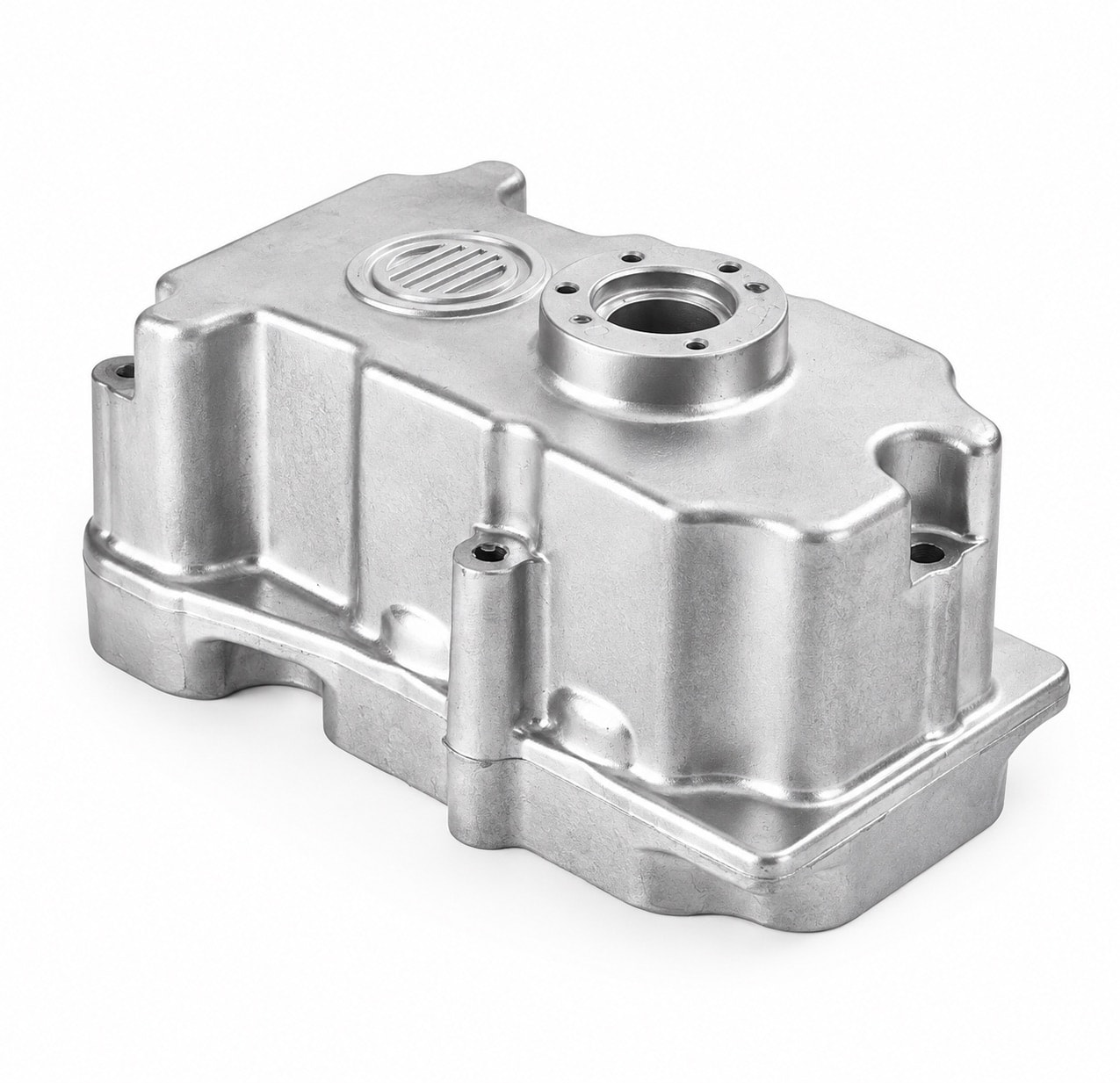
CASE STUDIES · Other sectors
Die-Cast Aluminum Gearbox Housing: Bearing-Bore Centre Distance Held to ±0.03 mm, Over 98% Pass Leak Test First Time
Bearing bosses opened porosity on boring, and bores machined apart from the joint face did not line up. Cored bosses and one-setup machining now hold ±0.03 mm and 98% first-pass leak test.
Part data
| Part name | Aluminum Gearbox Housing |
|---|---|
| Part type | Motor & gearbox housings |
| Application | Reduction gearbox for compact power equipment (upper case) |
| Customer type | Power-equipment manufacturer |
| Alloy | ADC12 (JIS H5302) |
| Envelope | 约 200 × 125 × 100 mm |
| Part weight | 约 1.2 kg |
| Wall thickness | 3.5 – 6.0 mm |
| Key requirements | Bearing-bore centre distance and parallelism, joint-face flatness, dowel-hole position, no porosity on machined faces, oil-tight case |
| Machining | Joint face milled, bearing bores bored and dowel holes reamed in one setup, flange holes drilled and tapped |
| Surface finish | Shot blasting |
| Delivered as | Machined part |
| In production since | 2024 |
* Figures shown are representative; actual values follow the drawing and DFM review.
Updated
Technical requirements
Bore accuracy
The input and output bearing bores are machined to H7, with the centre distance toleranced at ±0.03 mm and the two axes parallel within 0.03 mm. Centre distance and parallelism set the gear backlash and contact pattern; get them wrong and the gearbox runs noisy and hot and the teeth wear early.
Joint face and dowel holes
The joint face that meets the lower case must be flat within 0.05 mm, and the dowel holes located within φ0.05 mm of the bearing bores. The joint is sealed with liquid gasket, so a face out of flat weeps oil; the dowel positions decide whether the bearing bores line up once the two halves are closed.
Soundness and tightness
No porosity may break through on the bearing bores, the joint face or any other machined face. Every finished housing is leak tested at 0.05 MPa held for 15 s and judged on the customer's pressure-decay limit.
Engineering challenges
Shrinkage exposed in the bearing bosses after boring
The bearing bosses are the heaviest part of the casting, locally over 12 mm thick. On the first samples, pinholes appeared in the bore walls after fine boring. The bosses freeze last; the thinner walls round them solidify first and cut off the feed, so shrinkage collects at the boss centre. The casting has a dense skin, and once boring cuts through it the voids are left on the bearing seat.
Two setups: bores out of line with the joint face and dowels
At first the joint face and the bearing bores were machined in separate operations, the second re-located off the machined face. With the two halves closed, some housings showed the bores offset by as much as 0.08 mm, and bearings pressed in tight. Re-location error and fixture repeatability between the two setups had both stacked into the bore positions.
What we did
Core out the bosses, add overflows and vents where the fill ends (DFM review and die design)
Without giving up bearing support, we had the customer core out the outside of the bosses, bringing the heaviest section down from over 12 mm to about 8 mm. Flow simulation shows where the metal arrives and freezes last around the bosses, and that is where overflows and vents go, so cold metal and gas leave the cavity. First samples are X-rayed at the bosses and sectioned to confirm.
Cast the bores close to size so finishing stays in the dense layer (casting and CNC)
The bearing bores are cored close to size with 0.3–0.5 mm of stock per side, so the finished bore wall is still inside the dense layer instead of cutting it away. Bored walls are sampled every batch.
Joint face, bearing bores and dowel holes in one setup (CNC machining)
The joint face, both bearing bores and the dowel holes are now finished in a single setup on a machining centre, so every bore position comes from the same datum. Centre distance, parallelism and position are checked on the CMM each batch, and every bearing bore is plug-gauged.
100% leak test on finished parts (final inspection)
Every finished housing is leak tested and nothing that fails is released; results are archived by lot and traceable back to the casting batch.
Results in stable production
In stable production the bearing-bore centre distance holds within ±0.03 mm, porosity exposed on bored faces fell from about 4% to under 0.5%, more than 98% of housings pass the leak test first time, and the key bore dimensions run at CPK ≥ 1.33.
Questions on this part
Why does porosity only show up in a gearbox bearing bore after boring?+
A die casting chills fast at the surface and forms a dense skin, while shrinkage and gas porosity collect at the centre of heavy sections. The more stock you remove, the more of that skin goes and the likelier the voids are to open up. So bearing bores and sealing faces should be cast close to size with even stock, and heavy bosses cored out at the design stage.
A gearbox joint weeps oil — casting or machining?+
Check both. Porosity breaking out on a machined face, or through-shrinkage linking inside to outside, is a casting problem — look at wall thickness, gating and venting, and micro-leakers can be vacuum-impregnated if that has been agreed in advance. A face out of flat, deep tool marks or a dented joint face is a machining or handling problem. We control flatness and roughness on the joint face together, leak test before shipping, and pack in divided trays so faces are not knocked.
Capabilities and further reading
Have a part like this?
Start with the cost estimator to see how the price is built, or upload a drawing for us to review — we reply within 24 hours.