CASE STUDIES · Other sectors
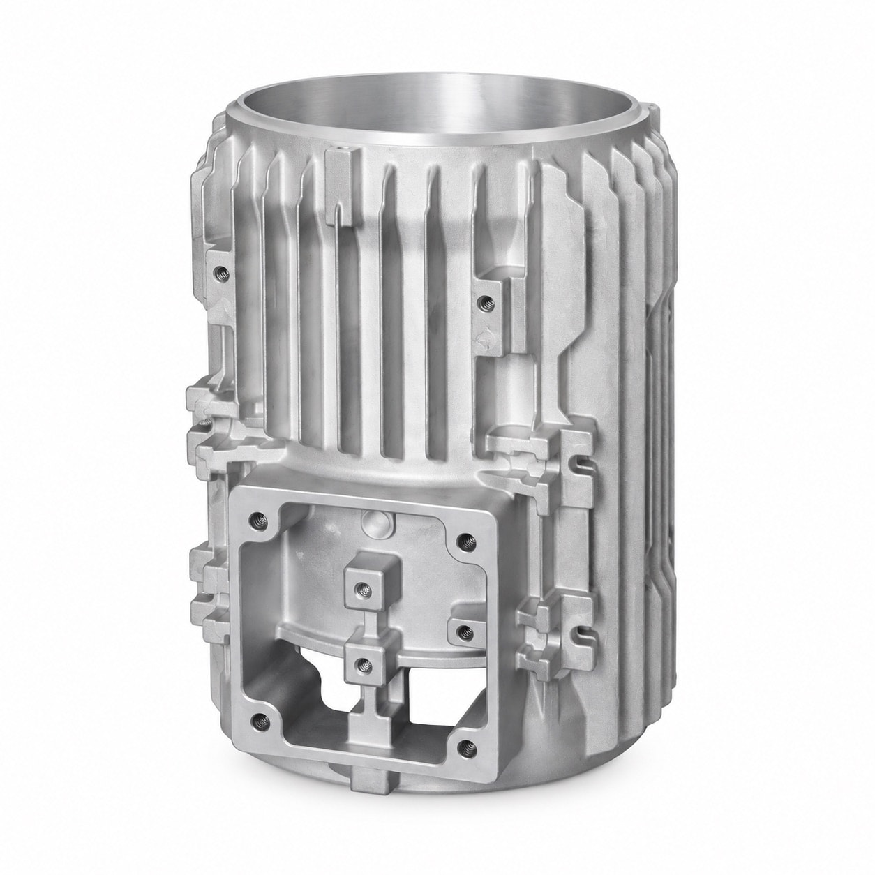
Die-Cast Finned Aluminum Motor Housing: Stator Bore Round Within 0.02 mm, End Pilots Coaxial Within φ0.03 mm
A thin-walled bore, two pilots and a coating step between roughing and finishing. A fin-located, axially clamped fixture and one datum throughout hold 0.02 mm roundness and φ0.03 mm coaxiality.
Part data
| Part name | Finned Aluminum Motor Housing |
|---|---|
| Part type | Motor & gearbox housings |
| Application | Industrial motor housing (external fins, integral terminal box) |
| Customer type | Electric-motor manufacturer |
| Alloy | ADC12 (JIS H5302) |
| Envelope | 约 Ø170 × 220 mm |
| Part weight | 约 2.6 kg |
| Wall thickness | 4.0 – 6.0 mm(散热筋 2.5 – 3.5 mm) |
| Key requirements | Stator-bore size and roundness, end-pilot coaxiality, end-face squareness, position of tapped holes on four faces |
| Machining | Stator bore, end pilots and faces turned; terminal-box face milled; tapped holes drilled on four faces |
| Surface finish | Shot blasting + powder coating |
| Delivered as | Machined part |
| In production since | 2024 |
* Figures shown are representative; actual values follow the drawing and DFM review.
Updated
Technical requirements
Stator bore
The stator bore takes the stator core as an interference fit; its diameter is held to H7 and its roundness to 0.02 mm. A bore out of round leaves an uneven air gap once the stator is pressed in, and vibration and noise rise with it.
Pilots and end faces
The pilots at each end locate the front and rear end shields and must be coaxial within φ0.03 mm, with the end faces square to the axis within 0.03 mm. Those pilots decide whether the two bearings share an axis — the key to a rotor that runs smoothly.
Tapped holes on several faces, and the coating
More than a dozen tapped holes sit on the base, the top, the terminal-box face and the sides — four directions in all — each with position and squareness requirements. The outside is shot-blasted and powder coated, and the coating may show no clamp marks or knocks.
Engineering challenges
A thin-walled housing that goes out of round when clamped
The main wall is only 4 mm. Turned in a three-jaw chuck, the bore measured good while clamped and sprang to more than 0.05 mm out of round when released. Radial clamping had squeezed the thin wall into a lobed shape that sprang back after machining — the classic "in-spec clamped, out-of-spec released".
Coating between roughing and finishing breaks the datum chain
The housing is roughed, then shot-blasted and powder coated, then finished to size. Every operation means a new setup, and each change of datum adds the previous operation's error to the next; after coating, the outside can neither serve as a datum nor be marked by the fixture.
What we did
An elastic fixture located on the fins, clamped axially (fixture design)
Instead of clamping radially, we designed an elastic-sleeve fixture that locates on the flanks of the fins: the sleeve seats against the fins to fix the housing radially, and the clamping force is applied along the axis, never on the thin wall. The stator bore is measured both clamped and released to compare the spring-back.
One datum — the two end pilots — from roughing to finishing (machining process)
The two end pilots are turned in the very first operation and become the common datum for everything after it. Finish turning after coating, milling the terminal-box face and drilling the tapped holes all locate back on them, so no error accumulates from changing datums. Wherever a locator touches the coating it carries a soft pad so nothing is marked.
Hold the locating fins consistent in the casting (die design)
Because the fixture locates on the fins, their position and thickness become part of the machining accuracy. The fins used for location carry their own tolerance on the die drawing, the wear on those cavities is measured at intervals, and first articles are checked on the CMM.
Tapped holes on four faces in one setup (CNC machining)
The tapped holes on all four faces are machined in one setup on a machining centre with a rotary table, rather than turning the part over face by face. Every stator bore is measured with a bore gauge, and coaxiality and squareness are checked on the CMM each batch.
Results in stable production
In stable production stator-bore roundness holds within 0.02 mm and end-pilot coaxiality within φ0.03 mm, coating damage from clamping fell from about 3% to under 0.3%, and the key dimensions run at CPK ≥ 1.33.
Questions on this part
How do you turn the bore of a thin-walled motor housing without distorting it?+
Keep the clamping force off the wall you are machining. The usual answers are to clamp axially instead of radially, or to spread the force with an elastic sleeve or dedicated soft jaws that follow the outside shape; split roughing from finishing and leave only a little stock for the finish cut. Verify by measuring roundness on the same part clamped and released and comparing the spring-back, not by trusting the clamped reading.
Why machine a coated housing both before and after coating?+
Blasting and coating change the size of machined faces and leave coating on the fits. The usual route is therefore: rough and establish the datum, blast and coat, then finish the stator bore, pilots and other fits, which end up bare. What matters is using one datum all the way through — every change of datum brings in new error. At quotation we agree with the customer which faces are masked and which are machined after coating.
Capabilities and further reading
Have a part like this?
Start with the cost estimator to see how the price is built, or upload a drawing for us to review — we reply within 24 hours.