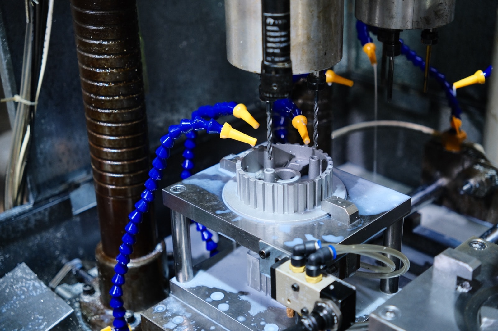
CAPABILITIES · Precision CNC Machining · 04
Precision CNC machining
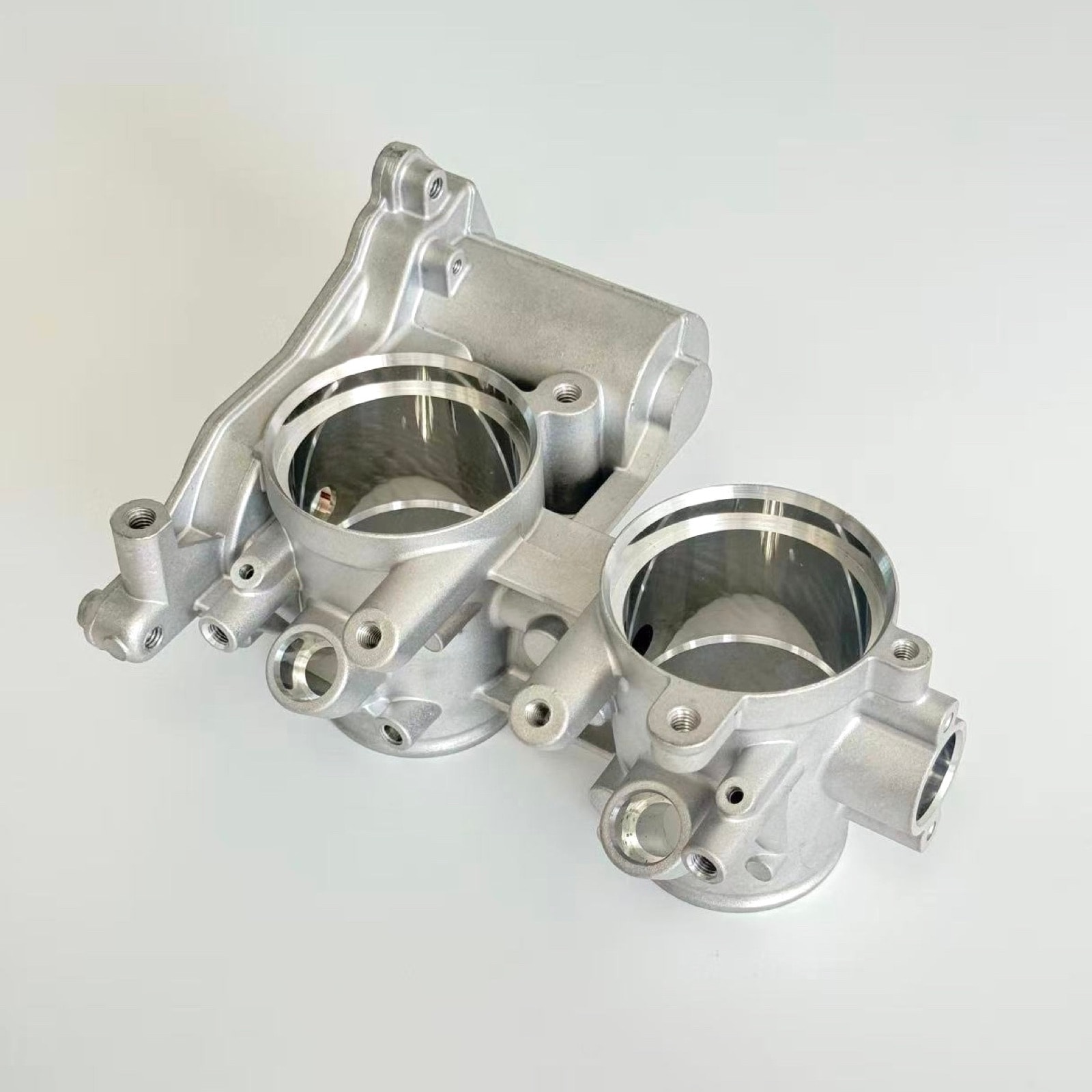
We machine die castings into ready-to-assemble parts on 30+ Haas and Brother machining centres, 30+ TAKISAWA CNC lathes and 50+ drilling and tapping units: down to ±0.005 mm on critical dimensions, critical bore patterns in a single setup, and CPK ≥ 1.33 on key characteristics. We machine our own castings and yours.
OVERVIEW
Precision machining
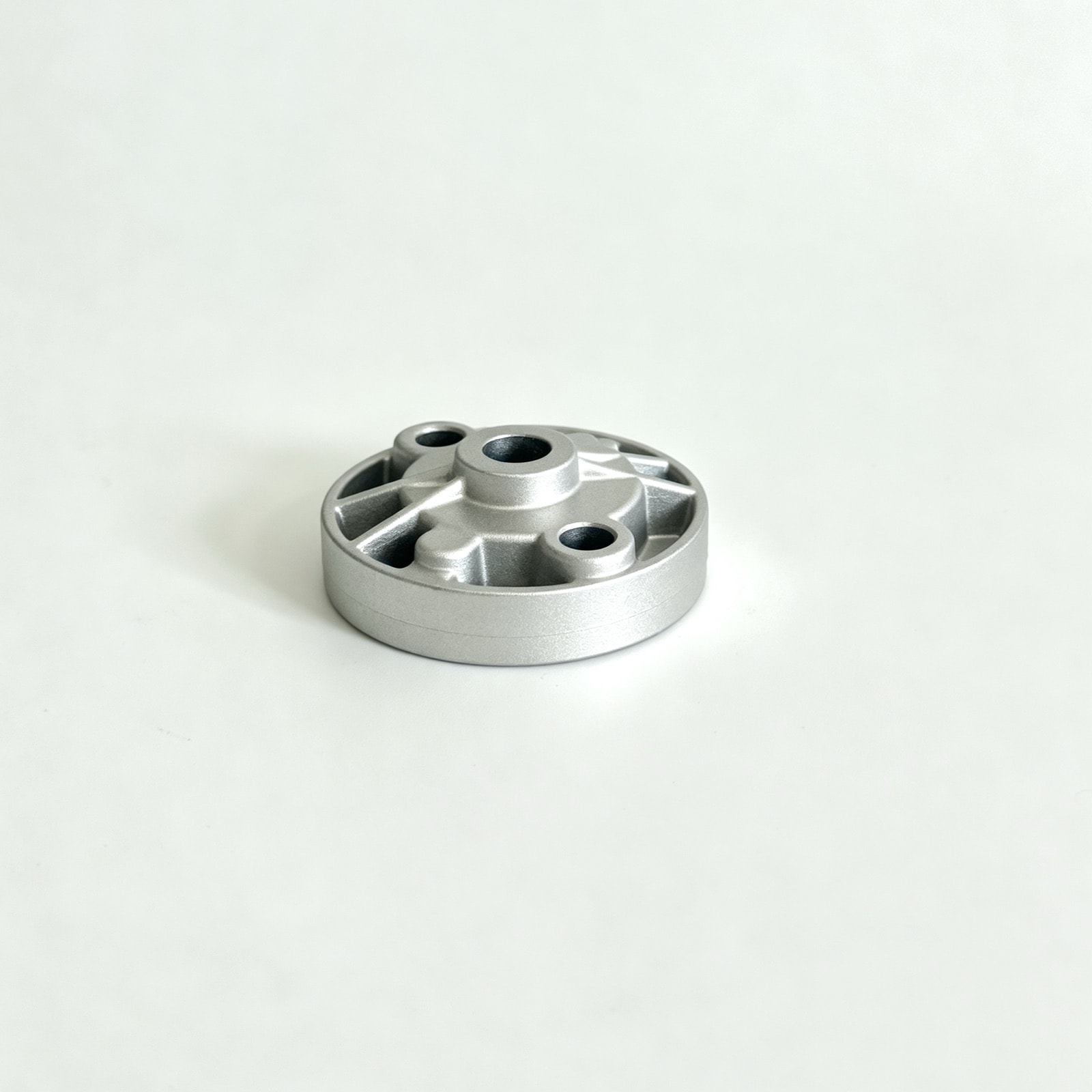
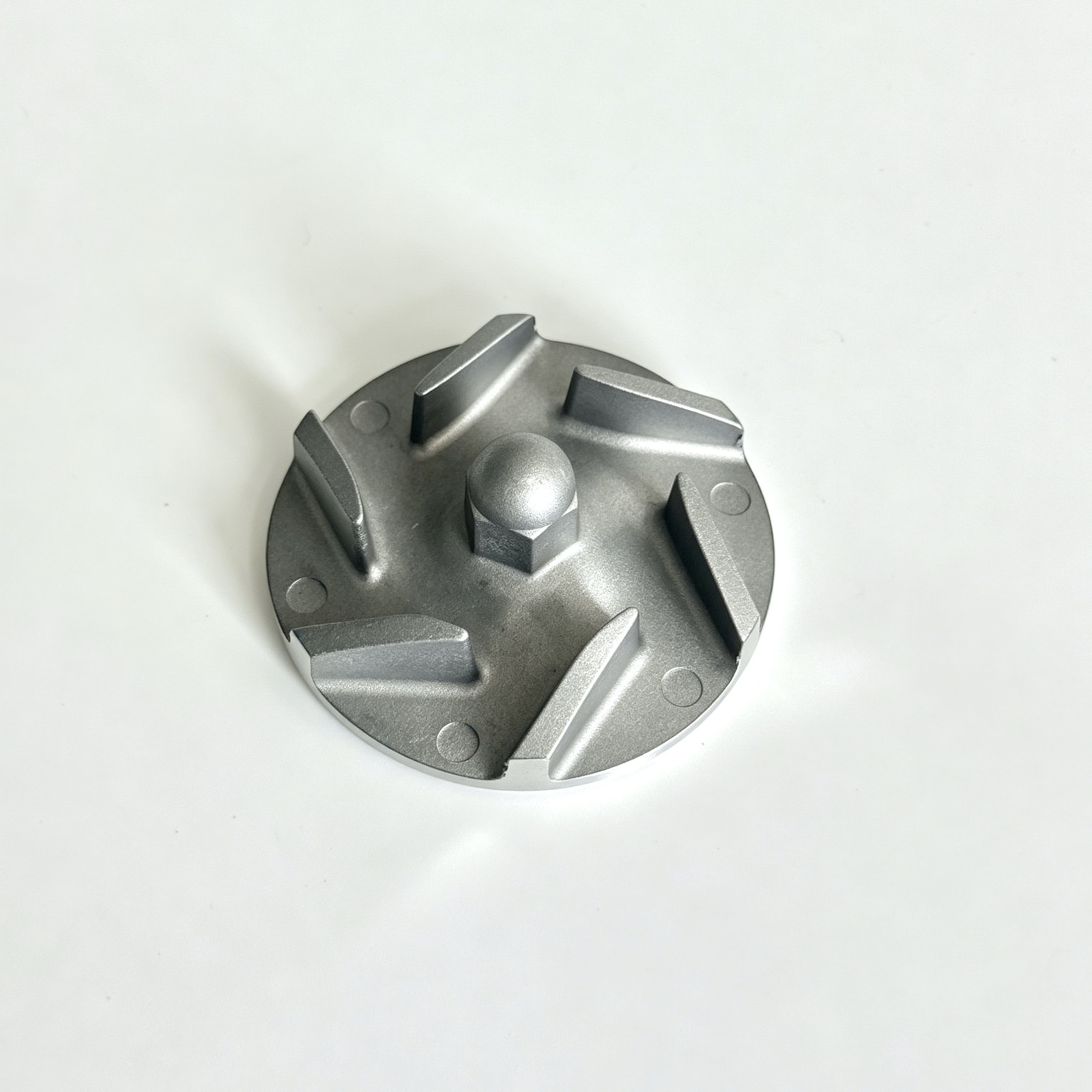
We take on facing, boring, drilling, tapping and turning of die castings, machining precision-fit features such as sealing faces, bearing seats, threaded holes and critical bore patterns, on zinc and aluminum parts alike. We can machine castings from our own foundry, or you can bring us your own castings for machining only.
On site we run 30+ Haas and Brother machining centres, 30+ TAKISAWA CNC lathes and 50+ dedicated drilling and tapping machines; with our other machining and support equipment, that makes more than 360 production machines in all.
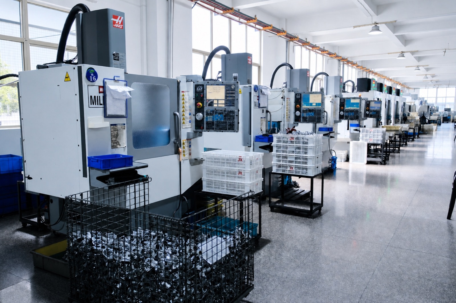
Capability at a glance
- Best tolerance
- Critical dimensions, depending on the part's geometry and size
- ±0.005 mm
- Bore concentricity
- Single setup
- φ0.05 mm
- Machined flatness (per 100 mm)
- For sealing and joint faces
- 0.05 mm
- Machined surface finish
- Ra 0.8 μm
- Process capability, key dimensions
- CPK ≥ 1.33
- CNC machines
- 30+ machining centres · 30+ lathes · 50+ drilling and tapping
- 110+
Casting and machining under one roof
Casting and machining happen in the same factory, so datums, machining stock and porosity criteria are settled together before the tool is built; if you send us castings from elsewhere, we confirm each of these with you at the first-article stage.
- 01
One datum throughout
We agree the casting datum with you at the DFM stage; the first operation builds the machining datum from it, and every later operation uses the same one.
- 02
Single setup
Four-axis machining centres cut several faces and the critical bores in one setup, avoiding the 0.03–0.05 mm a second setup adds.
- 03
No clamping distortion
Parts are held in dedicated fixtures, soft jaws or vacuum chucks, with roughing and finishing done as separate operations; each part is measured both clamped and released to keep distortion under control.
- 04
Porosity rules
Criteria for exposed porosity are agreed in writing before production; high-silicon aluminum is cut with PCD or diamond tooling for tool life and surface quality.
Machining stock
0.2–0.3 mm on ordinary faces and 0.1 mm on precision fits such as seal seats and bearing bores, keeping as much of the casting's dense skin as possible so less internal porosity is exposed.
Quality and inspection
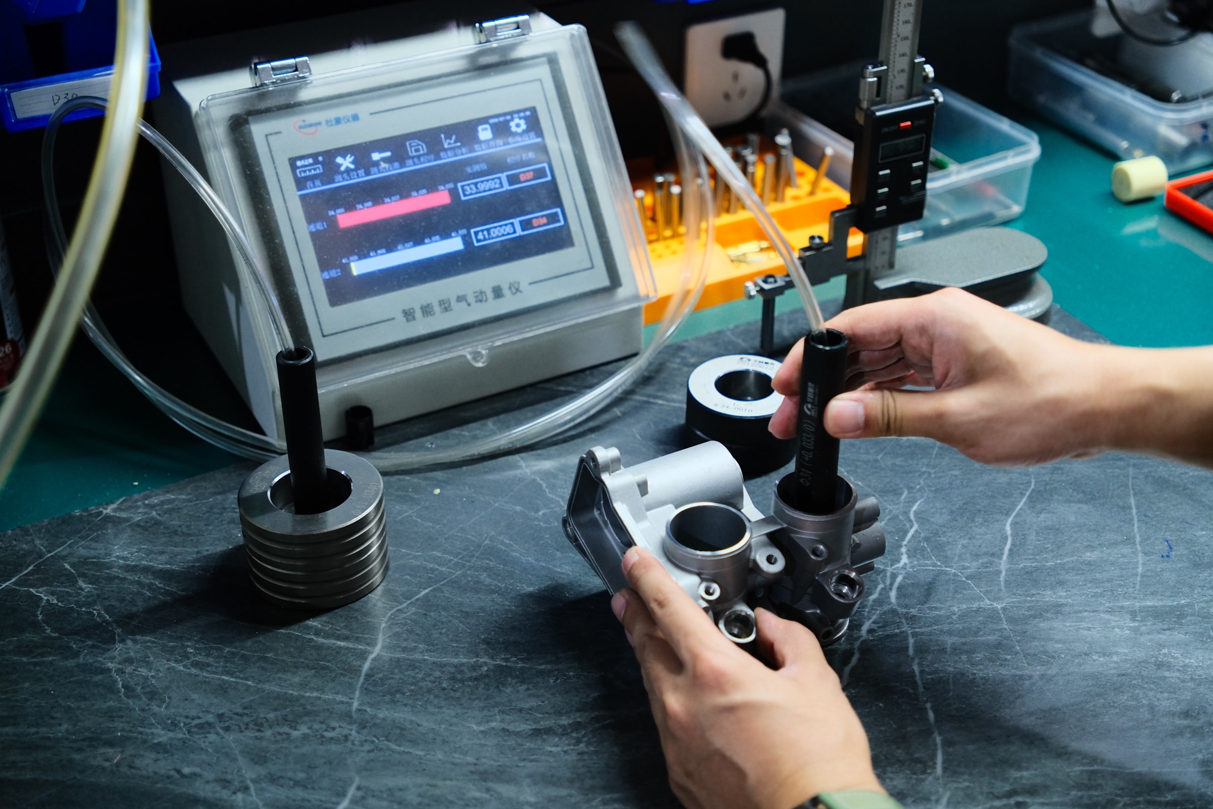
We work strictly to our ISO 9001:2015 quality system; the specific tests and the form of the reports are set to your requirements.
- 1
CMM measurementCMM measurement to ±0.003 mm, with dimensional inspection reports issued to your requirements.
- 2
First article and capabilityA first-article report available for the first part; CPK analysis on key dimensions, with CPK ≥ 1.33 required.
- 3
Distortion re-checkParts with tight flatness requirements are measured after machining and again after 24 hours, and released only if both measurements pass.
- 4
TraceabilityIf a quality issue arises, we provide an 8D report on request, fully documenting the root-cause analysis and corrective actions.
LEAD TIME
Machining lead time
- 01First-article machining and program proving2–3days
- 02Fixture design and build7–12days
- 03Pilot run and capability study5–10days
- 04Production per batch (machining only)15–25days
These are estimates: a new part takes 14–25 days from first-article machining to pilot run, 7–12 of them for fixtures; in production, machining-only orders take 15–25 days per batch (parts we also cast follow the casting lead time). Castings you supply follow the same timetable.
CASE STUDIES
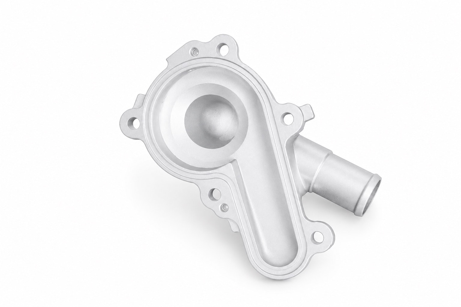
Parts made with this capability
FAQ
Questions we get
What machining equipment do you have?+
On site we run 30+ Haas and Brother machining centres, 30+ TAKISAWA CNC lathes and 50+ dedicated drilling and tapping machines; with our other machining and support equipment, that makes more than 360 production machines in all.
How accurate is your CNC machining, and which dimensions should go to CNC?+
Critical dimensions can be held to ±0.005 mm at best, depending on the part's geometry and size; critical bore concentricity is φ0.05 mm, machined flatness 0.05 mm per 100 mm, and machined surface finish Ra 0.8 μm. Fits, sealing faces, bearing seats and bores that casting tolerance cannot guarantee are best left to CNC. At the DFM stage we list cast-controlled and machining-controlled characteristics separately and confirm them with you.
How is concentricity held on a critical bore pattern?+
It is secured at two levels together. In casting, we place the related bores and the locating face on the same die half, not across the parting line; in machining, a four-axis machining centre bores them together in a single setup, with no second setup. With both in place, concentricity holds consistently within φ0.05 mm. If the casting itself spans the parting line, concentricity is usually limited to about φ0.09 mm; we raise this with you early at the DFM stage and assess the process feasibility together.
Can you do machining only, on castings we supply?+
Yes. We machine castings from our own foundry and also take castings you supply. For supplied castings, we suggest sending the drawing and samples first; at the first-article stage we confirm the datums, machining stock and porosity criteria with you, then build the fixtures and run the batch.
How do you judge a part when machining exposes porosity?+
It depends on where the porosity appears and what the part does. A common grading: any visible porosity exposed on a sealing or load-bearing face means scrap; on a non-sealing machined face, a single pore no larger than an agreed diameter (say Ø0.5 mm) with no clustering is acceptable; and on pressure-tight parts the final leak test governs — if it passes, it ships, and micro-leakers are impregnated and re-tested as agreed. We confirm each of these criteria with you in writing at the DFM stage, so both sides judge production parts the same way.
FURTHER READING
Technical articles
- TOLERANCES
Die Casting Tolerance vs CNC Machining Tolerance
Understand the difference between die casting and CNC machining tolerances, how tolerance stack-up occurs, and when machining is worth the added cost.
- MACHINING
Which Features of a Die-Cast Part Should Be CNC Machined?
Learn which die-cast features should be machined, which should remain as-cast, and how engineers and buyers can balance tolerance, tooling, porosity, and total production cost.
- MACHINING
Why Die-Cast Parts Fail During CNC Machining: The Hidden Connection Between Casting Quality and Machining Performance
Learn why die-cast parts leak, chip, crack, or go out of tolerance during CNC machining — and how buyers and engineers can prevent failures through better casting controls.