CASE STUDIES · Motorcycle & Two-Wheeler
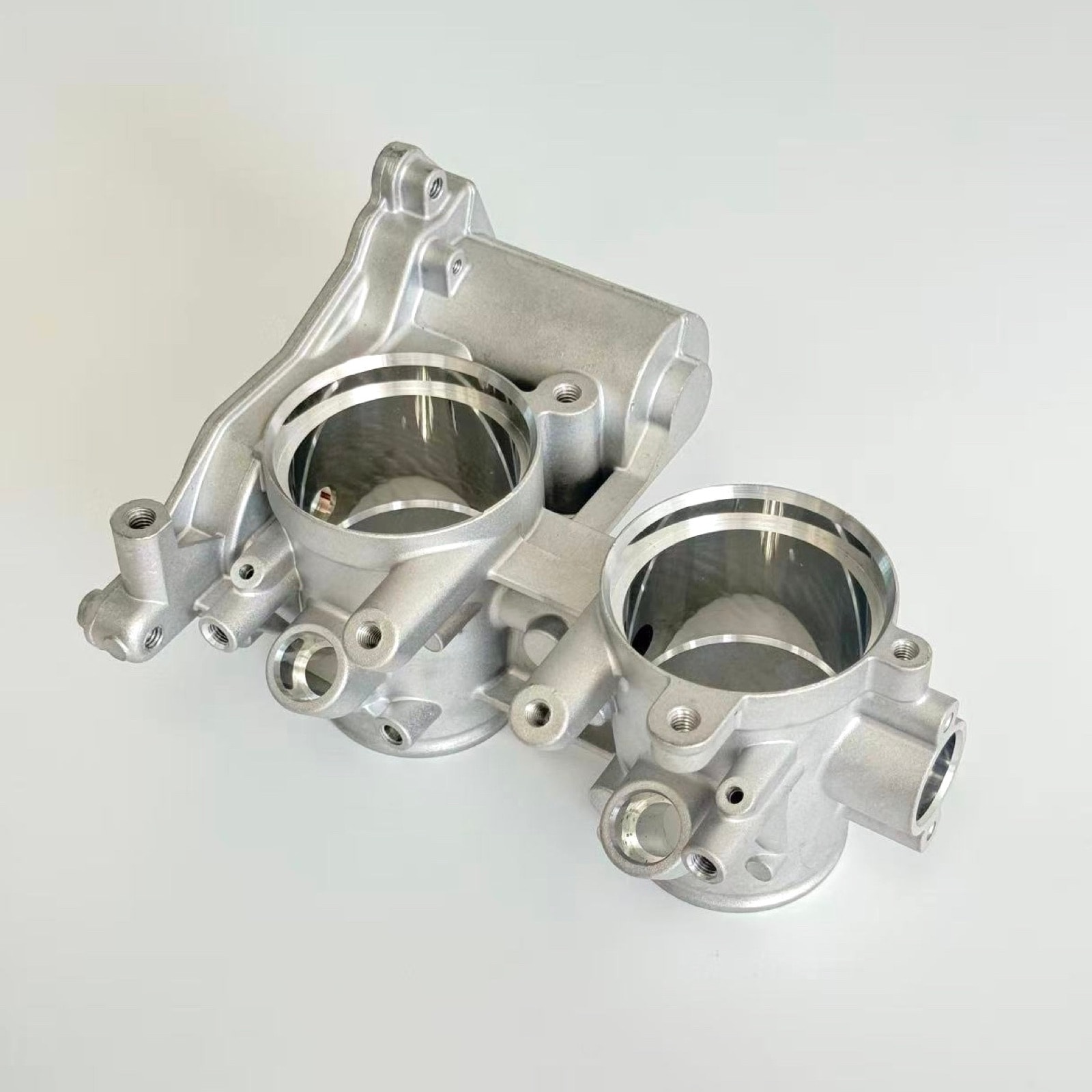
Die-Cast Motorcycle Twin Throttle Body: Bore Diameters Matched Within 0.02 mm
Machined in two setups, the twin bores differed by up to 0.05 mm and the engine idled rough. One-setup boring and soft jaws now match them within 0.02 mm.
Part data
| Part name | Motorcycle Twin Throttle Body |
|---|---|
| Part type | Carburetor & fluid control |
| Application | Fuel-injection intake system, twin-cylinder motorcycle |
| Customer type | Tier-1 supplier to a Chinese motorcycle OEM |
| Alloy | ADC12 (JIS H5302) |
| Envelope | 约 165 × 95 × 70 mm |
| Part weight | 约 520 g |
| Wall thickness | 3.0 – 5.0 mm |
| Key requirements | Bore concentricity, diameter match, shaft-bore true position, intake tract tightness |
| Machining | Both bores in one setup, shaft bores reamed, flange faces milled, drilled and tapped |
| Surface finish | Shot blasting |
| Delivered as | Machined part |
| In production since | 2024 |
* Figures shown are representative; actual values follow the drawing and DFM review.
Updated
Technical requirements
Dimensional accuracy
Each throttle bore is toleranced at ±0.02 mm, and the two bores on one body may differ by no more than 0.02 mm. That difference sets how evenly the two cylinders breathe; too large a gap unbalances them and roughens the idle.
Geometric tolerances
The two throttle bores must be concentric within φ0.05 mm and the throttle-shaft bore located within φ0.1 mm true position. Shaft position decides whether the butterflies close evenly in their bores and turn without binding.
Pressure tightness
The intake tract is leak tested at 0.05 MPa held for 20 s, with no leak allowed. A leaking tract lets unmetered air into the engine and upsets the mixture.
Engineering challenges
Matching the two bores
Machined in two setups, the bores differed by up to 0.05 mm — enough to unbalance the two cylinders and roughen the idle. A second setup adds datum-transfer error, and tool wear keeps accumulating between the two operations, so the diameters never converge.
Distortion from clamping a thin wall
Bores measured good while clamped, then sprang back by more than 0.03 mm once released. A 3 mm intake wall deforms elastically under normal clamping force and springs back after machining — the classic "in-spec clamped, out-of-spec released".
What we did
Both throttle bores bored in one setup (CNC machining)
In two setups, datum transfer and the tool wear between operations both add to the diameter difference. We bore both bores in a single setup on a shared set of tool offsets, so the two diameters move together. The difference is checked on the first article and every 2 hours.
Dedicated soft jaws with controlled clamping (fixture design)
The intake walls are only 3 mm thick, so normal clamping deforms them elastically and they spring back by more than 0.03 mm on release. We use dedicated soft jaws with a controlled, repeatable clamping force, and measure the bores both clamped and released to compare the spring-back.
Parting line kept off the sealing band, flange formed in one die half (die design)
A parting line across the sealing band leaves flash and mismatch that become leak paths. We route the parting line clear of the sealing band and form the whole flange face in one die half; first articles are leak tested and the sealing face is blue-checked.
Results in stable production
In stable production the two bore diameters match within 0.02 mm, more than 98% of bodies pass the leak test first time, and key dimensions run at CPK ≥ 1.33.
Questions on this part
How do you guarantee the two bores match on a twin throttle body?+
Bore both in a single setup and let them share one tool-compensation set. Split across two setups, datum-transfer error and the tool wear between operations stack up and the difference typically lands at 0.04–0.05 mm; in one setup it holds within 0.02 mm. In production we sample the difference between the bores every two hours rather than checking each bore against its own tolerance in isolation.
How do you control distortion when machining a thin-wall throttle body?+
Three things: replace point clamping with wide soft jaws or a dedicated fixture, at a clamping force set per part and repeatable; split roughing from finishing with a stress-relief step between; and leave only 0.1 mm on precision faces so finishing does not introduce fresh stress. We verify by measuring the same part clamped and released and comparing the spring-back, rather than trusting the clamped reading.
Related cases
Capabilities and further reading
Have a part like this?
Start with the cost estimator to see how the price is built, or upload a drawing for us to review — we reply within 24 hours.