CASE STUDIES · Motorcycle & Two-Wheeler
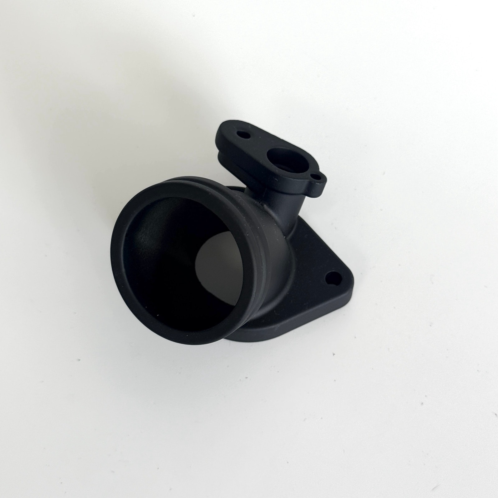
Die-Cast Motorcycle Intake Manifold Adapter: Flanges Parallel Within 0.1 mm, Over 99% First-Pass Leak Yield
Milled in two setups, the flanges ran 0.2 mm out of parallel and the gasket leaked. One-setup machining and 100% leak testing now hold 0.1 mm.
Part data
| Part name | Motorcycle Intake Manifold Adapter |
|---|---|
| Part type | Carburetor & fluid control |
| Application | Motorcycle intake system |
| Customer type | Motorcycle OEM and aftermarket |
| Alloy | ADC12 (JIS H5302) |
| Envelope | 约 85 × 60 × 55 mm |
| Part weight | 约 150 g |
| Wall thickness | 3.0 – 4.5 mm |
| Key requirements | Flange-face parallelism and flatness, tract tightness |
| Machining | Both flange faces milled, tract bored, drilled and tapped |
| Surface finish | Blasting + black coating |
| Delivered as | Finished part |
| In production since | 2023 |
* Figures shown are representative; actual values follow the drawing and DFM review.
Updated
Technical requirements
Geometric tolerances
The two flange faces must be parallel within 0.1 mm and each flat within 0.05 mm. Parallelism decides whether the gasket is compressed evenly; too much error and it only seals on one side.
Sealing
The tract is leak tested at 0.05 MPa held for 20 s, with no leak allowed. A leak draws extra air at idle and leans out the mixture.
Appearance
The part ships black coated; the coating must be even with no runs, judged against the limit sample.
Engineering challenges
Parallelism error from machining the faces separately
Milled in two setups the faces ran up to 0.2 mm out of parallel, so the gasket was crushed on one side only. Datum-transfer error between setups lands straight on parallelism, and a gasket is very sensitive to uneven crush.
Tightness of the thin-wall tract
Micro-leaks in the tract wall let extra air in at idle and lean out the mixture. The outer wall of the bend is the end of fill, where cold shuts and sub-surface porosity collect; connect the two and you have a leak path.
What we did
Both flange faces machined in one setup (CNC machining)
Machined in two setups, the datum-transfer error lands straight on parallelism. We machine both flanges in a single setup, check parallelism on every part and blue-check the sealing faces.
Gate into the heavy flange so the outer tract wall does not fill last (die design)
If the outer wall of the bend is the end of fill, cold shuts and sub-surface porosity collect there and can link into a leak path. We gate into the heavy flange to change the fill order, confirmed by simulation and short shots.
100% leak test on finished parts (final inspection)
Every finished part is pressure-decay tested with the result logged, and none that leaks is released.
Results in stable production
In stable production flange parallelism holds within 0.1 mm, more than 99% pass the leak test first time, and intake-leak complaints after fitting are below 0.2%.
Questions on this part
Where do you start when an intake adapter leaks?+
Three places, in order. First the flange faces — uneven gasket crush from poor flatness or parallelism is the usual cause. Second the tract wall itself, which a pressure-decay test separates out. Third the tapped holes: tap deeper than designed and you break into the tract. We test the first two on 100% of parts before shipping and control the third in the machining program.
Can you ship this kind of small part fully finished?+
Yes. Normally casting, CNC and leak testing happen in-house while blasting and coating go to a long-standing partner shop — but the process spec, incoming and outgoing inspection and the final quality responsibility stay with us, so you deal with one supplier. If you nominate your own finisher we will work with them; we just set out in the contract who carries which responsibility.
Related cases
Capabilities and further reading
Have a part like this?
Start with the cost estimator to see how the price is built, or upload a drawing for us to review — we reply within 24 hours.