CASE STUDIES · Heat Sinks & Structural Enclosures
Die-Cast Shaped Aluminum Heat Sink Plate: 2 mm Fins Over 99% Filled, Ejection Drag Marks Cut From 4% to Under 0.5%
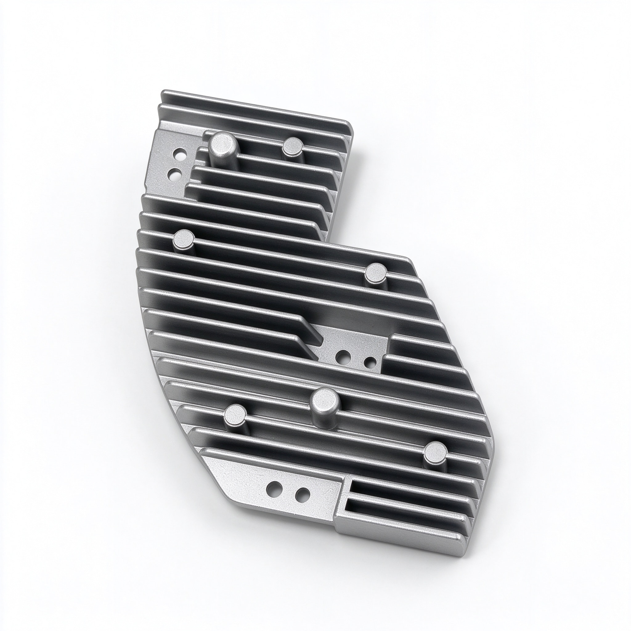
An irregular plate with 2 mm fins and seven bosses among them. Flow-led gating, spot-cooled boss cores and more draft give over 99% fin fill and cut drag marks from 4% to under 0.5%.
Part data
| Part name | Shaped Aluminum Finned Heat Sink Plate |
|---|---|
| Part type | Heatsinks & electronic enclosures |
| Application | External heat sink plate for power and control modules |
| Customer type | Power-equipment manufacturer |
| Alloy | ADC12 (JIS H5302) |
| Envelope | 约 190 × 150 × 30 mm |
| Part weight | 约 480 g |
| Wall thickness | 2.0 – 3.0 mm(散热齿 2.0 mm) |
| Key requirements | Complete fin fill, sound bosses of consistent height, contact face flat to 0.05 mm per 100 mm |
| Machining | Contact face milled; mounting holes drilled and tapped |
| Surface finish | Bead blasting |
| Delivered as | Machined part |
| In production since | 2025 |
* Figures shown are representative; actual values follow the drawing and DFM review.
Updated
Technical requirements
Fins
The plate carries nearly 20 parallel fins, 2.0 mm thick and about 12 mm tall — roughly 6:1. No fin may be short-filled, broken or bent, and every plate is checked visually against a master.
Bosses
Seven cylindrical bosses stand among the fins to locate and support the plate in the assembly, with a height tolerance of ±0.1 mm. No shrinkage porosity is allowed inside them, judged by X-ray sampling to ASTM E505 level 2.
Contact face
The underside sits against the power devices and carries their heat; after milling it must be flat to 0.05 mm per 100 mm with a finish of Ra 3.2 or better.
Engineering challenges
An irregular outline leaves the far fin tips short
The outline is an irregular polygon with angled edges and cut-outs, so every fin is a different length and the flow distance to each tip varies widely. At trial, the ends of the short fins far from the gate and the fins along the angled edge were the first to come out short with rounded tips.
Bosses among thin fins become hot spots
At about 10 mm across, each boss is far heavier than the 2 mm fins beside it and is the last part of the plate to solidify. Trial castings showed shrinkage at the boss roots under X-ray and slight sinks on the boss tops, and boss height wandered with them.
Dense fins drag on ejection and edge fins bend
Nearly 20 fins grip the die at once, so ejection takes a lot of force. Early trials showed drag marks on the fin flanks, and a few fins near the edge were bent on ejection — about 4% of parts in all.
What we did
Gating set by flow simulation, with overflows and vents at the tips (die design)
We compared several gating layouts in flow simulation and settled on feeding along the fins, so metal runs down the slots towards the tips. Overflows and vents were added along the angled edge and at the ends of the short fins, and the die runs at 200–240 ℃. The first article and every shift are checked against the master.
Spot-cooled boss cores and filleted roots (die design and DFM)
Each boss core has its own spot cooling so the boss solidifies closer to the fins around it, and at DFM the customer agreed an R1.5 mm fillet at each boss root to soften the change in section. The boss area is X-rayed each batch and boss height is sampled on a gauge.
More draft, polish in the direction of draw, evenly spread ejectors (die design)
Fin draft went from 1° to 1.5° per side and the fin slots are polished in the direction of draw. Ejector pins are spread across the fin roots and under the bosses so the whole plate comes out evenly and the edge fins are no longer bent.
Contact face milled in one pass, holes in the same setup (CNC machining)
Located on the three mounting pads, the underside is milled in one pass and the mounting holes are drilled and tapped in the same setup; flatness is checked on the CMM each batch.
Results in stable production
In stable production more than 99% of plates fill the fins completely, the bosses meet ASTM E505 level 2 on X-ray, drag marks and bent fins fell from about 4% to under 0.5%, and the contact face holds 0.05 mm per 100 mm.
Questions on this part
How thin should the fins be to be worth it?+
Thinner and closer means more surface, but the process window narrows sharply and the yield loss can cost more than the thermal gain is worth. Design at 1.5–2.5 mm, with about 1.2 mm as the limit, a height-to-thickness ratio no worse than 6:1 and pitch at least twice the fin thickness. In practice, work out the surface area the thermal design needs, then see whether taller fins or a larger base can deliver it instead of thinner fins — both carry far less process risk.
Why do bosses on a finned plate tend to shrink?+
A boss is much heavier than the fins around it and solidifies last; with nothing left to feed its shrinkage, it ends up with porosity inside and a sink on top. There are three usual fixes: core the boss out or thin it wherever possible; spot-cool the boss core so it freezes with its surroundings; and fillet the root so the section does not change abruptly. If a boss will be tapped or used as a seating face, settle that at DFM and plan X-ray sampling where needed.
Related cases
Capabilities and further reading
Have a part like this?
Start with the cost estimator to see how the price is built, or upload a drawing for us to review — we reply within 24 hours.