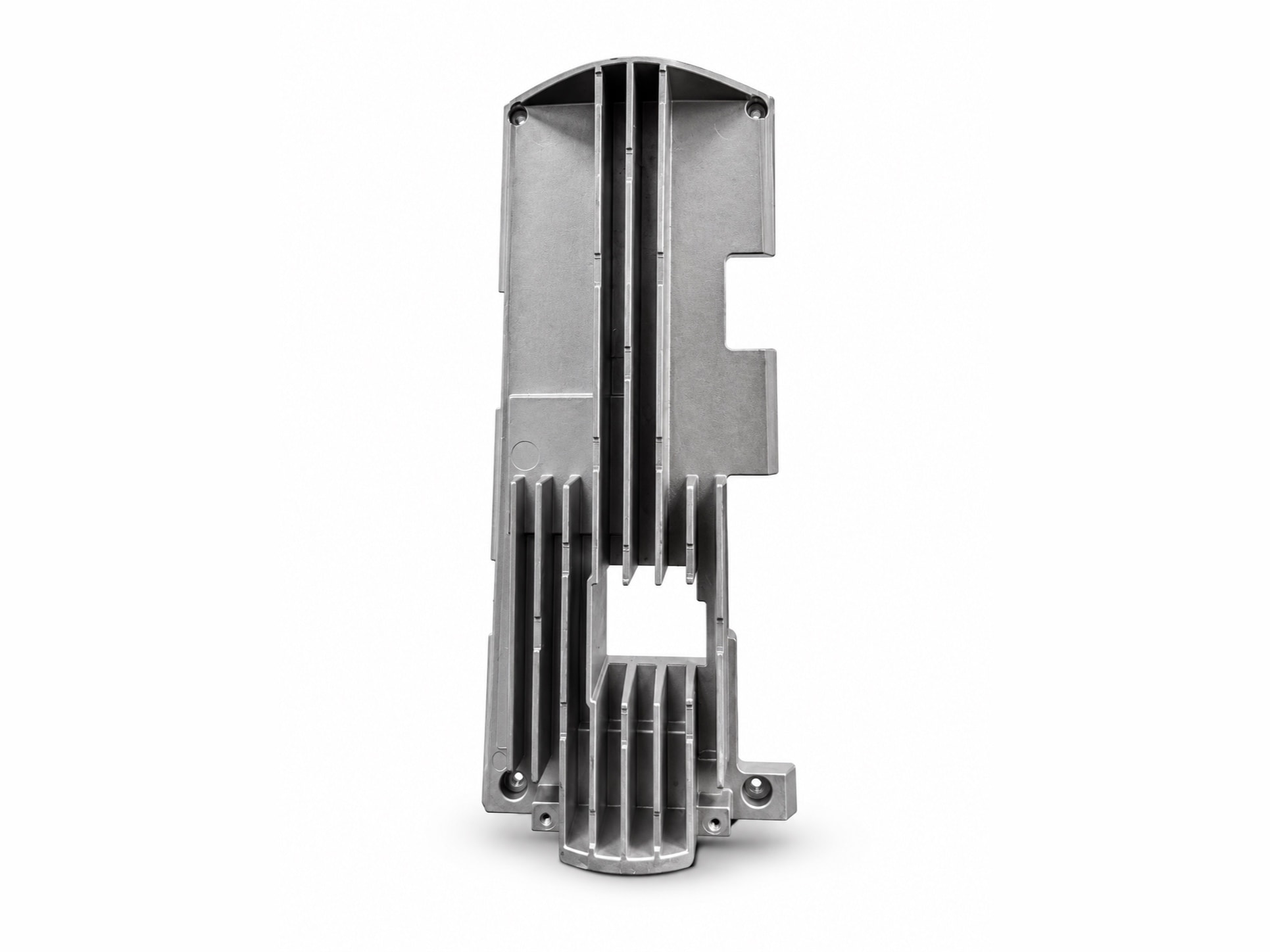
CASE STUDIES · Heat Sinks & Structural Enclosures
Die-Cast Long Aluminum Heat Sink Base Housing: 320 mm Long, As-Cast Warp Cut From 0.6 mm to Within 0.15 mm
A 320 mm housing with long internal fins and an asymmetric section warped 0.6 mm. Multi-point gating, zoned cooling and stress relief brought it within 0.15 mm, base flat to 0.05 mm/100 mm.
Part data
| Part name | Long Aluminum Heat Sink Base Housing |
|---|---|
| Part type | Heatsinks & electronic enclosures |
| Application | Heat sink base housing for power modules in energy-storage and charging equipment |
| Customer type | Energy-storage and charging-equipment manufacturer |
| Alloy | ADC12 (JIS H5302) |
| Envelope | 约 320 × 115 × 35 mm |
| Part weight | 约 780 g |
| Wall thickness | 2.5 – 3.5 mm(内部散热筋 2.0 mm) |
| Key requirements | As-cast warp over the full length, base flat to 0.05 mm per 100 mm, long fins free of cold laps, mounting-hole position |
| Machining | Base milled; mounting and tapped holes drilled |
| Surface finish | Bead blasting |
| Delivered as | Machined part |
| In production since | 2025 |
* Figures shown are representative; actual values follow the drawing and DFM review.
Updated
Technical requirements
Shape and fins
The housing is about 320 mm long and 115 mm wide, close to 3:1. Inside, several fins run lengthways — the longest about 200 mm, all 2.0 mm thick — with a square cable window in the middle and a cut-out along one side. No fin may show cold laps or short fill.
Flatness
The base sits against the power devices and is milled flat to 0.05 mm per 100 mm. To keep the machining stock even, the casting may warp no more than 0.2 mm over its full length as it leaves the die.
Hole positions
The corner mounting holes and the tapped holes at the foot are positioned to 0.1 mm so the housing lines up with the equipment frame.
Engineering challenges
A long part that bows along its length
The fins are concentrated in the middle, one side is cut away and there is a window in the centre, so the section is asymmetric. Uneven sections and cooling made the two sides shrink differently: trial castings came out of the die with about 0.6 mm of warp over the length, three times the limit, leaving too little stock at one end for milling and too much at the other.
Cold laps at the far end of the long fins
The longest fin runs about 200 mm at 2 mm thick. By the time metal reaches its far end it has cooled noticeably, and where two flow fronts meet near the end of the fin they leave cold laps and flow lines.
Distortion after milling a large face
Once a layer is milled off the base, residual casting stress redistributes, and when the part is re-measured a day or two later its flatness is out.
What we did
Multi-point gating along the long side, set by flow simulation (die design)
Flow simulation led us to replace the single gate with several fan gates along the long side, so metal advances along the fins together and the longest flow path is shorter. The point where the fronts meet was moved out into overflows beyond the fin ends, and the cold lap is trimmed away with them.
Cooling zoned to the section, and a setting fixture after ejection (die design and casting)
The cooling circuits are zoned separately for the dense-fin area and for the side with the window and cut-out, keeping the two sides at a similar temperature. After ejection each part cools on a setting fixture that holds it straight, and the first part of every shift is measured for warp over its full length.
Roughing and finishing split, with stress relief between (CNC machining)
The base is rough-milled to establish a datum, stress-relieved, then finish-milled, and flatness is measured after finishing and again 24 h later. Mounting and tapped holes are located from the finished base and two tooling holes and machined in a single setup.
Results in stable production
In stable production as-cast warp over the full length came down from about 0.6 mm to within 0.15 mm, the milled base holds 0.05 mm per 100 mm and moves no more than 0.02 mm after 24 h, and cold laps on the fins are below 0.5%.
Questions on this part
Why do long die castings warp, and how is it controlled?+
A long part shrinks a lot along its length, and any asymmetry in wall thickness, fin layout or cooling makes the two sides shrink differently, so it bows. Control usually comes in three steps: make the section as symmetric and the fins as evenly spread as possible at DFM; zone the die cooling to keep both sides at a similar temperature; and cool the part on a setting fixture after ejection. Faces that need tight flatness keep enough stock to be milled.
What thermal conductivity does a die-cast heat sink have?+
Die-cast aluminum sits around 90–120 W/(m·K) — ADC12 about 92–96, AlSi12 slightly higher. That is well below the roughly 220 of pure aluminum, because alloying elements (silicon and copper especially) scatter phonons. If the thermal design has no margin, switching alloy buys little: increase surface area, move to extrusion, or use a copper base. We can help estimate from the actual geometry at quotation, though the formal thermal simulation is best done on your side.
Related cases
Capabilities and further reading
Have a part like this?
Start with the cost estimator to see how the price is built, or upload a drawing for us to review — we reply within 24 hours.