CASE STUDIES · Motorcycle & Two-Wheeler
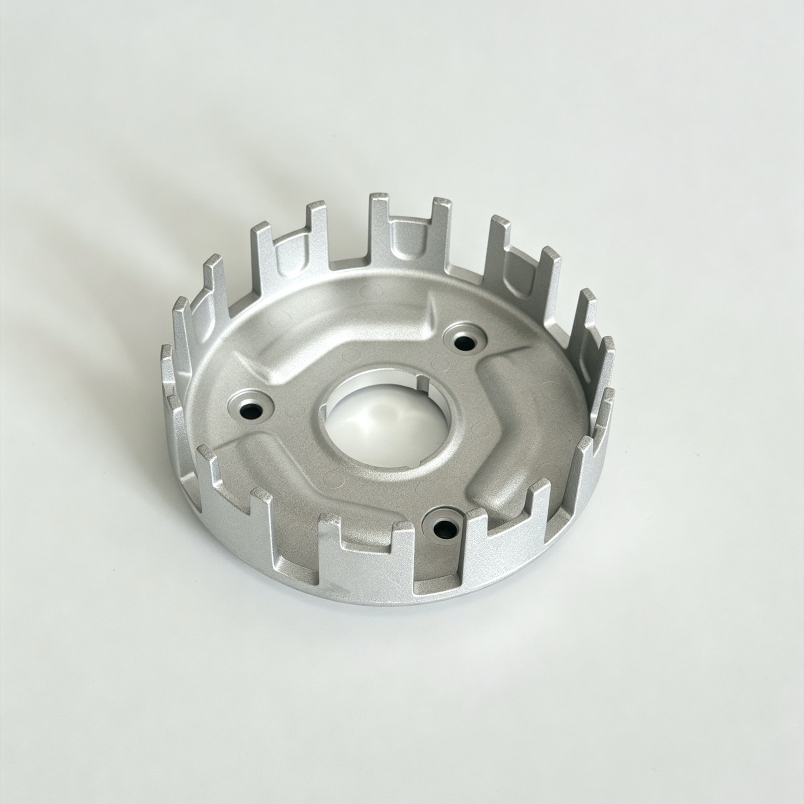
Die-Cast Motorcycle Clutch Basket: Slot Width Held to ±0.05 mm, Zero Binding Complaints
Slot widths once varied by 0.08 mm between batches and the friction plates bound. Core cooling, scheduled core changes and 100% gauging now hold ±0.05 mm.
Part data
| Part name | Motorcycle Clutch Basket |
|---|---|
| Part type | Rotating & drive parts |
| Application | Motorcycle engine clutch assembly |
| Customer type | Chinese motorcycle OEM |
| Alloy | ADC12 (JIS H5302) |
| Envelope | 约 Ø150 × 45 mm |
| Part weight | 约 330 g |
| Wall thickness | 3.0 – 6.0 mm |
| Key requirements | Slot-width consistency, slot-to-bore concentricity, face runout |
| Machining | Centre bore, faced ends, rivet holes drilled |
| Surface finish | Shot blasting |
| Delivered as | Machined part |
| In production since | 2022 |
* Figures shown are representative; actual values follow the drawing and DFM review.
Updated
Technical requirements
Dimensional accuracy
The slot width on this clutch basket is toleranced at ±0.05 mm and the centre bore at ±0.02 mm. Slot width sets the sliding clearance of the friction plates; the centre bore is the datum for assembly and for every machining operation.
Geometric tolerances
The slots must be concentric with the centre bore within φ0.1 mm, and face runout is limited to 0.05 mm. Concentricity decides whether every slot takes an even share of the load; runout affects how squarely the plate stack seats.
Surface
The slot flanks must be free of drag marks and flash, judged against a limit sample agreed with the customer. A drag mark or burr on a flank catches the friction-plate tabs as they slide, which is what makes a clutch bind.
Engineering challenges
Heat concentrating at the slots causes soldering and drag
After a production run the slot flanks show drag marks, and in bad cases aluminum solders to the slot root. The slot cores are slender with little surface to shed heat; once they run hot the aluminum sticks to the die face and tears on ejection.
Slot width drifting between batches
The same die gave slot widths varying by more than 0.08 mm between batches, so the friction plates fitted loose or tight by turns. The slot cores wear and distort through thermal cycling, and die-temperature swings add a shrinkage difference on top.
What we did
Conformal cooling in the slot cores to hold the root temperature (mould design)
The slot cores are long and thin with little surface to shed heat, so they run hotter than anything else in the die. We run conformal cooling channels inside them to bring the root temperature down, which removes the cause of soldering and drag marks. Die temperature is monitored in line during production, and the flanks are checked on the first article.
Slot cores inspected and replaced by shot count (die maintenance)
Thermal cycling slowly wears and distorts the slot cores, and that is the main source of batch-to-batch drift in slot width. We log shots against the cores, measure the slot-width trend every 50,000 shots, and replace the cores at 120,000 shots on schedule rather than waiting for parts to go out of tolerance.
100% go/no-go gauging of slot width (final inspection)
Every finished basket has its slot width checked with a dedicated go/no-go gauge, and nothing that fails is released. Samples are also measured on the CMM at intervals to confirm the gauges themselves are still judging correctly.
Results in stable production
In stable production the slot width holds within its ±0.05 mm tolerance and binding complaints at the customer's assembly line have dropped to zero. The slot cores are inspected every 50,000 shots and replaced at 120,000.
Questions on this part
Why not simply machine the clutch slots to size?+
You can, but it multiplies the cost. The slots are deep, so milling needs long-reach tooling — slow, expensive in tools, and the thin teeth deflect under cutting load. Cast the slots and, with the cores properly cooled and maintained, ±0.05 mm is repeatable, which is all the friction plates need. Save CNC for the centre bore and end faces, where the fit actually matters.
What fixes drag marks on the slot flanks?+
First work out whether it is temperature or release agent. Marks that appear only after a run and cluster at the slot root usually mean the cores are running hot and the metal is soldering — attack that with conformal cooling and spray timing. Marks from the first shots usually mean uneven spray or a degraded core finish; polish the cores and re-set the spray. Nitriding or a PVD coating on the cores pushes soldering much further out.
Related cases
Capabilities and further reading
Have a part like this?
Start with the cost estimator to see how the price is built, or upload a drawing for us to review — we reply within 24 hours.