INDUSTRIES · Robotics & Automation
Die castings for robotics and automation
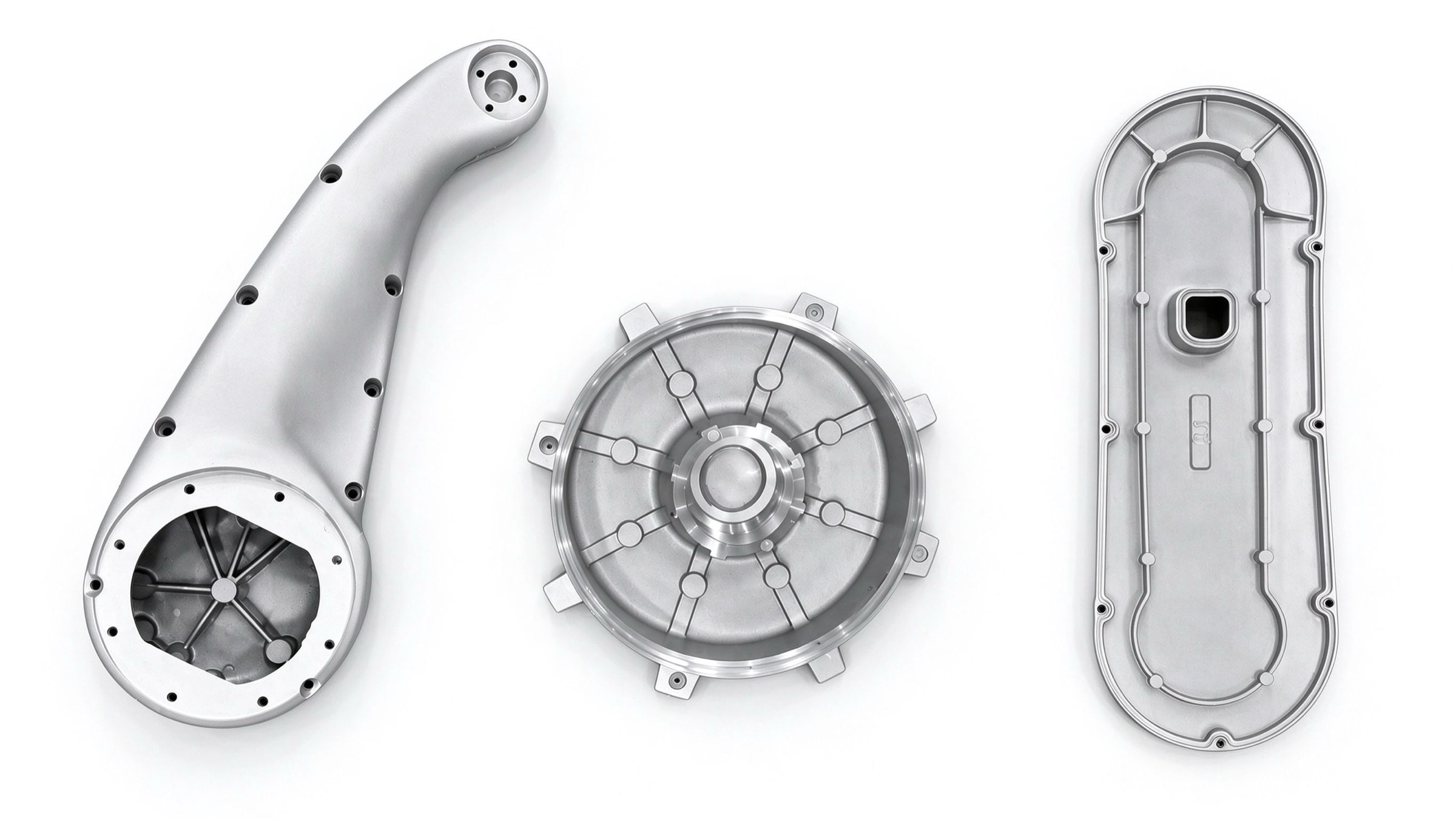
Robot joint, gearbox and actuator housings need coaxial bearing bores, square pilots, low weight, good heat paths and sound metal — the same things we hold every day on our motorcycle and pump production parts. We can cast and machine housing parts for robotics programmes.
- Bores in one setup, φ0.05 mm coaxiality
- Coaxiality and squareness on the CMM
- Squeeze-fed bosses, sound machined faces
- DFM for moving from billet to die casting
OVERVIEW
What we can do for robotics programmes
We can take on aluminum housing parts for robots and automation equipment: joint motor housings and end covers, harmonic, RV and planetary gearbox housings, actuator housings, flanges and brackets, and controller and drive enclosures. Parts run 20 g–5.5 kg, and the 800 t machine takes parts up to about 950 cm² projected area.
What makes these housings hard: the bearing bores at each end must be coaxial, the pilot and mounting faces square to the axis, the bearing bosses are the heaviest sections and prone to shrinkage, and the whole part has to stay light while carrying heat away from the motor. We squeeze-feed the bosses, leave only 0.1–0.3 mm of stock, finish bores and pilot in one setup on a machining centre, and check coaxiality and squareness on the CMM.
If your part is machined from billet today, a die-cast blank finished by machining is worth considering once the design is frozen and volumes rise. At DFM we mark up draft, wall thickness, lightening pockets and machining datums, and quote the tooling and piece price for the cast route.
RELATED CASES
Production parts with the same requirements
These cases come from the motorcycle and pump sectors, not robotics, but they share what robot housings demand: coaxial bearing bores, bores finished in one setup and sound metal inside.
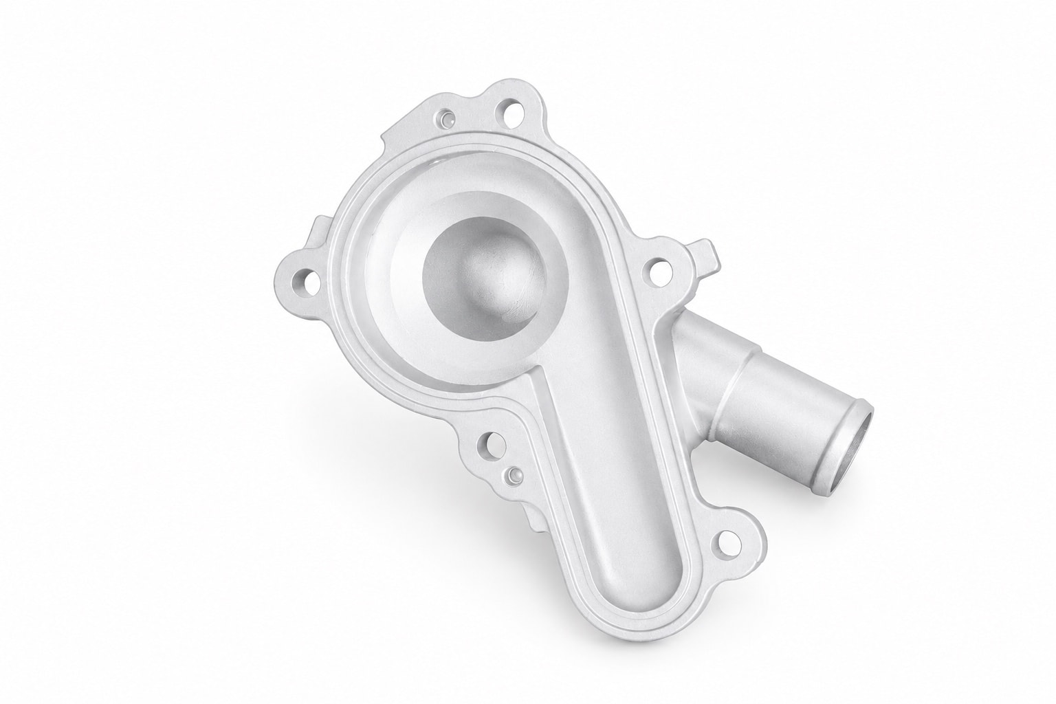
Motorcycle Aluminum Water Pump Housing
ADC12 · 约 380 g
Three suppliers had failed on this housing, with 6.2% leaking on test. A new parting line, reworked gating and venting, and one-setup boring cut leaks to under 0.5%.
Read the case →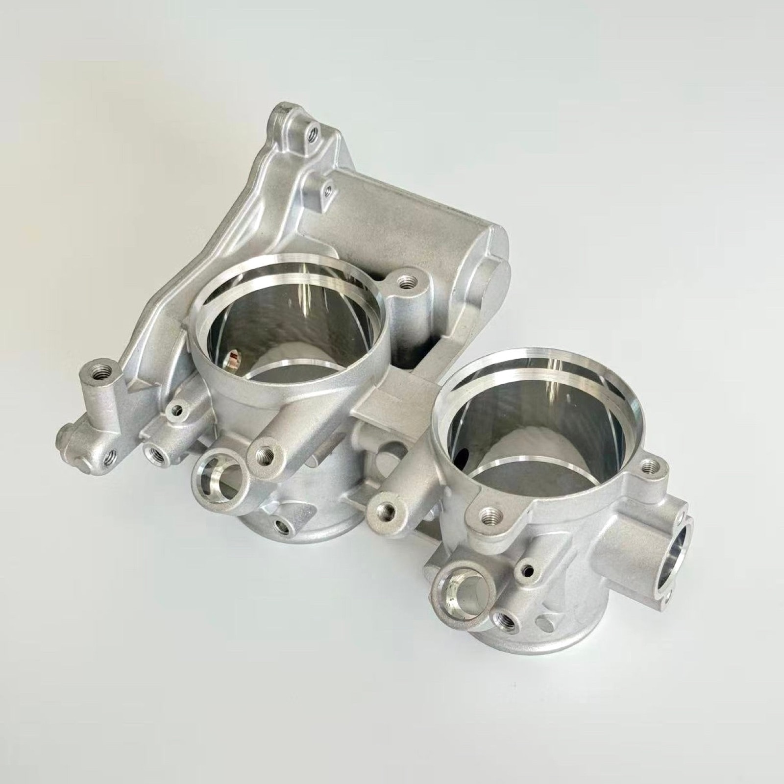
Motorcycle Twin Throttle Body
ADC12 · 约 520 g
Machined in two setups, the twin bores differed by up to 0.05 mm and the engine idled rough. One-setup boring and soft jaws now match them within 0.02 mm.
Read the case →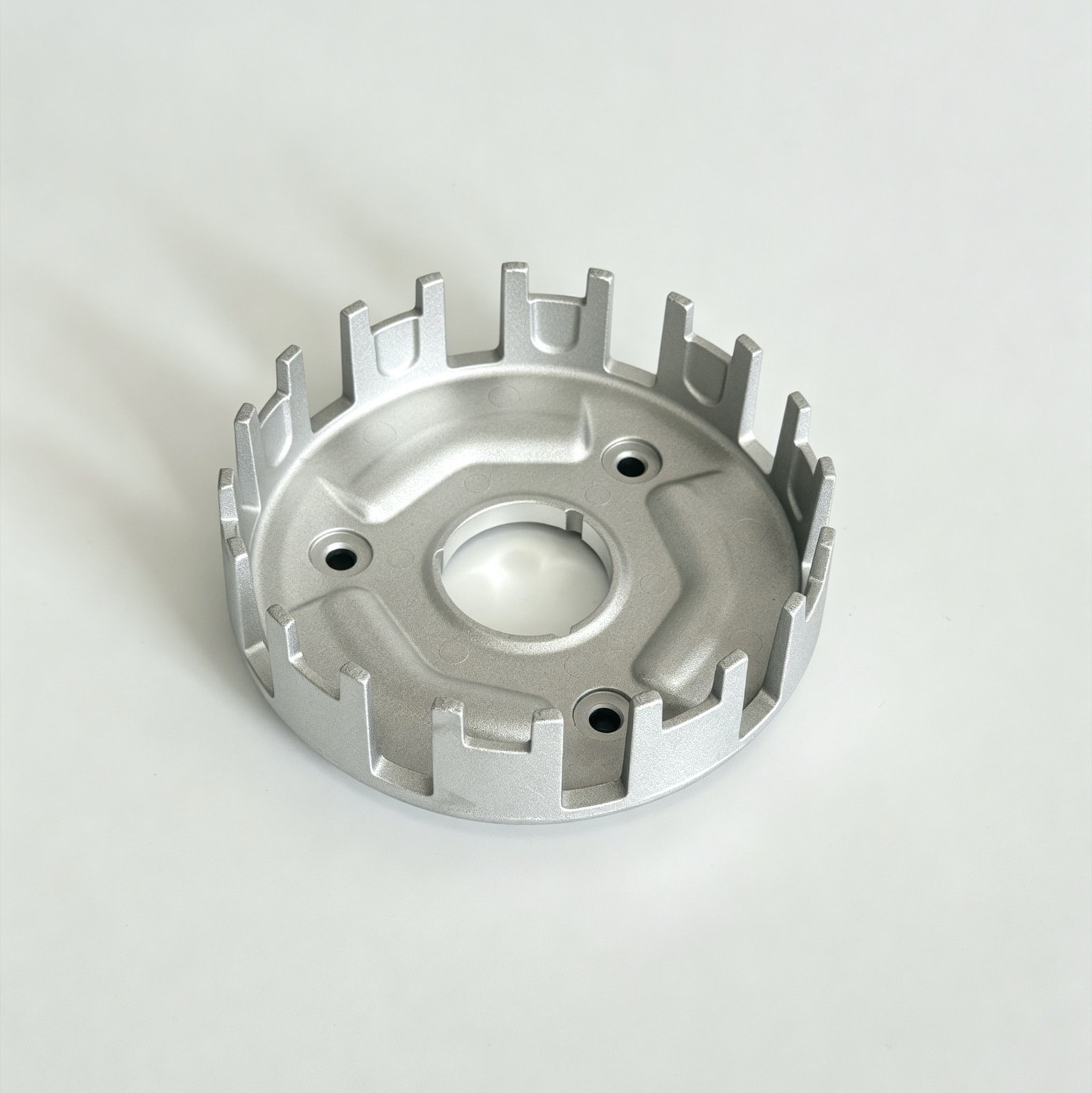
Motorcycle Clutch Basket
ADC12 · 约 330 g
Slot widths once varied by 0.08 mm between batches and the friction plates bound. Core cooling, scheduled core changes and 100% gauging now hold ±0.05 mm.
Read the case →TERMS
Working with us
Sampling lead time
Metal 3D-printed or CNC-machined prototypes before tooling; samples from a simplified or modified tool in 7–15 days; a production tool normally takes 30–45 days to build and T1 trials 3–5 days, and a pilot run can follow sample approval.
MOQ
No MOQ for samples and pilot runs; production from 500 pcs.
Documentation
Material certificates, dimensional and first-article (FAI) reports, CMM reports, X-ray sampling reports and RoHS/REACH reports can ship with the goods on request.
Nominated suppliers
We buy to your nominated grade or alloy supplier and can fit your nominated bearing brands, with responsibilities set out in the contract.
HOW A PROJECT RUNS
From drawing to production: how we work with you
- 01
Drawing review and DFM
We confirm the bearing-bore, pilot and mounting-face requirements, and for billet designs mark up draft, wall thickness and lightening pockets.
- 02
Tool design and build
Flow simulation finds shrinkage risk at the heavy bosses; the tool is built in-house with bores and locating faces kept on one die half.
More → - 03
T1 samples and first-article report
Full dimensional results, CMM coaxiality and squareness reports and material certificates, with X-ray results where needed.
- 04
Pilot run
After sample approval a pilot run proves cycle time and process capability; production starts once key characteristics reach CPK ≥ 1.33.
- 05
Production and delivery
The control plan drives first-article, patrol and final checks, traceable to melt lot; production from 500 pcs, 25–35 days per batch.
WHAT WE GUARANTEE
Three things robot housings need, and how we deliver them
- 01
Coaxiality: bores and pilot in one setup
Bores and pilot are finished in one setup on a machining centre, with no datum transfer; at the level of our production parts that is φ0.05 mm coaxiality and ±0.02 mm bearing seats, checked on the CMM.
See the case → - 02
Soundness: no porosity on machined faces
The bearing bosses are squeeze-fed and the casting carries only 0.1–0.3 mm of stock, so finished faces stay in the dense skin; X-ray sampling where needed.
More → - 03
Light weight and heat paths
Walls are kept even, heavy sections cored out, and cooling fins added on the outside where the motor needs them — routinely 1.5–2.5 mm thick at up to 6:1.
More →
PROCESSES
Processes, materials and finishes we use
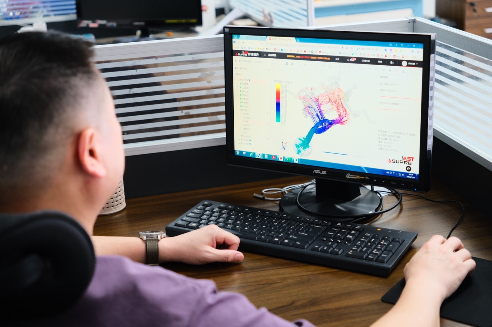
Tool design and build
Designed and built in-house with flow simulation before steel is cut; aluminum tools last around 100k shots and belong to you.More →
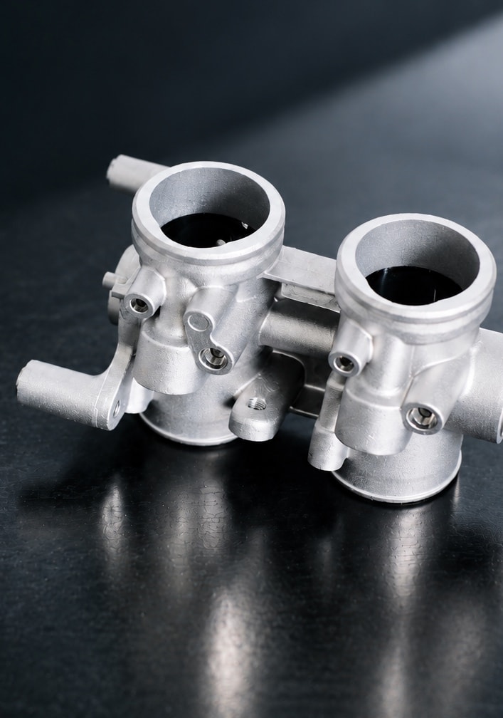
Aluminum die casting
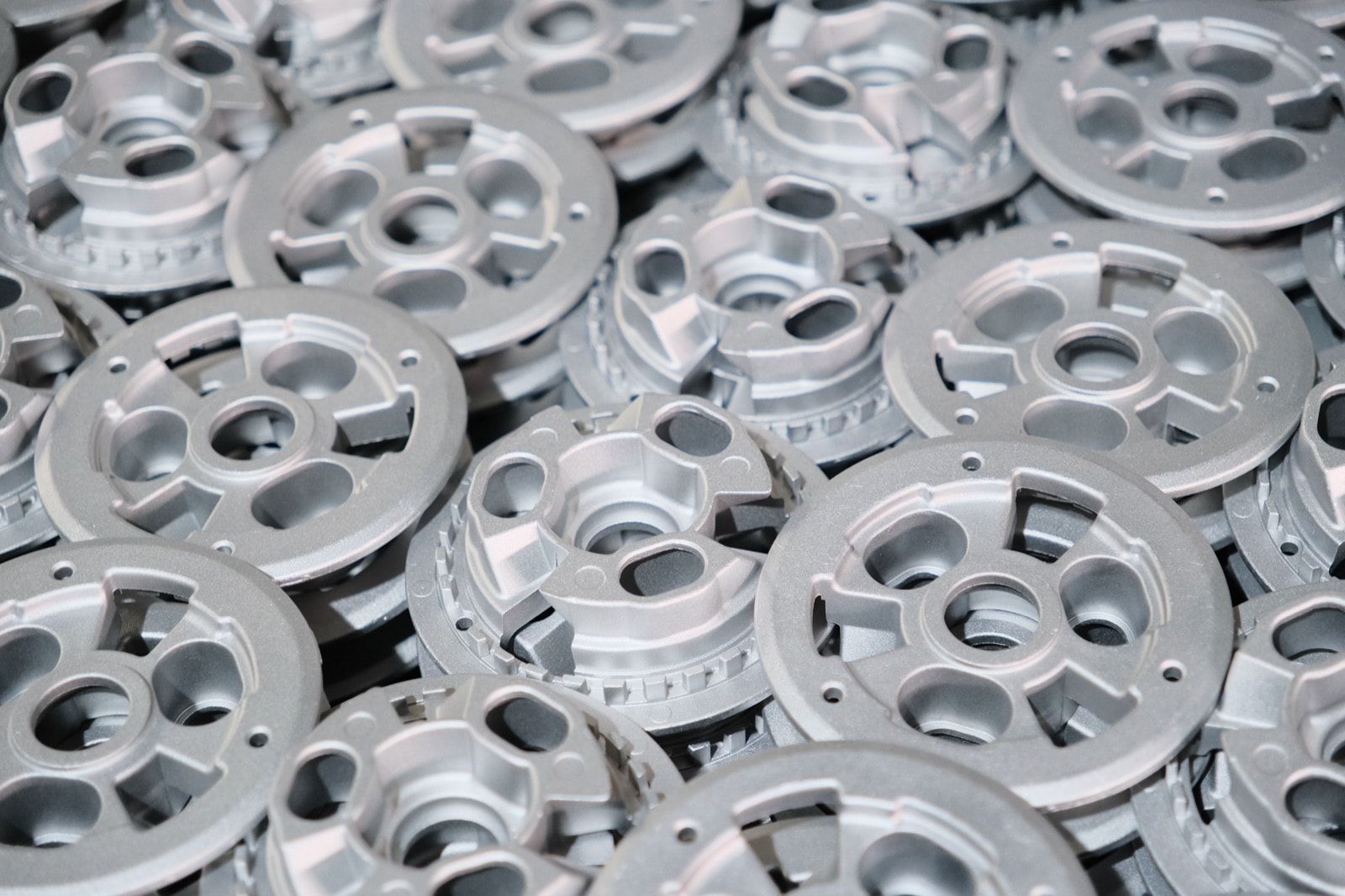
Ten machines from 160 to 800 t; housings usually in ADC12, with A380 and A360 available; local squeeze on heavy sections.More →
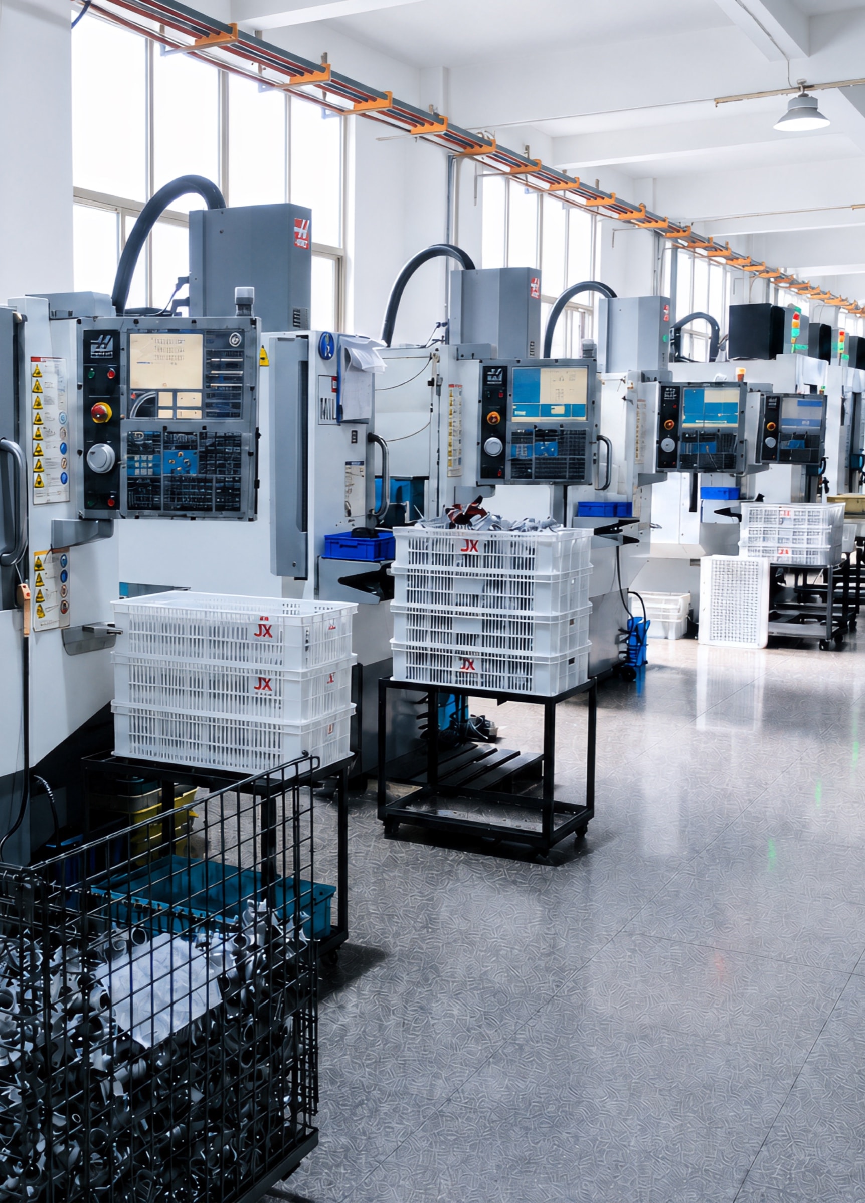
CNC machining
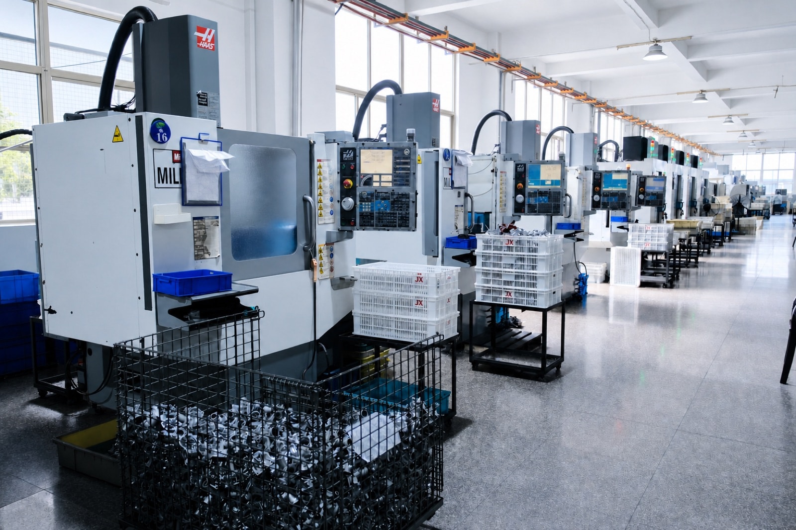
Haas and Brother machining centres and TAKISAWA lathes; bearing bores and pilot in one setup, checked on a CMM.More →
Finishing and assembly
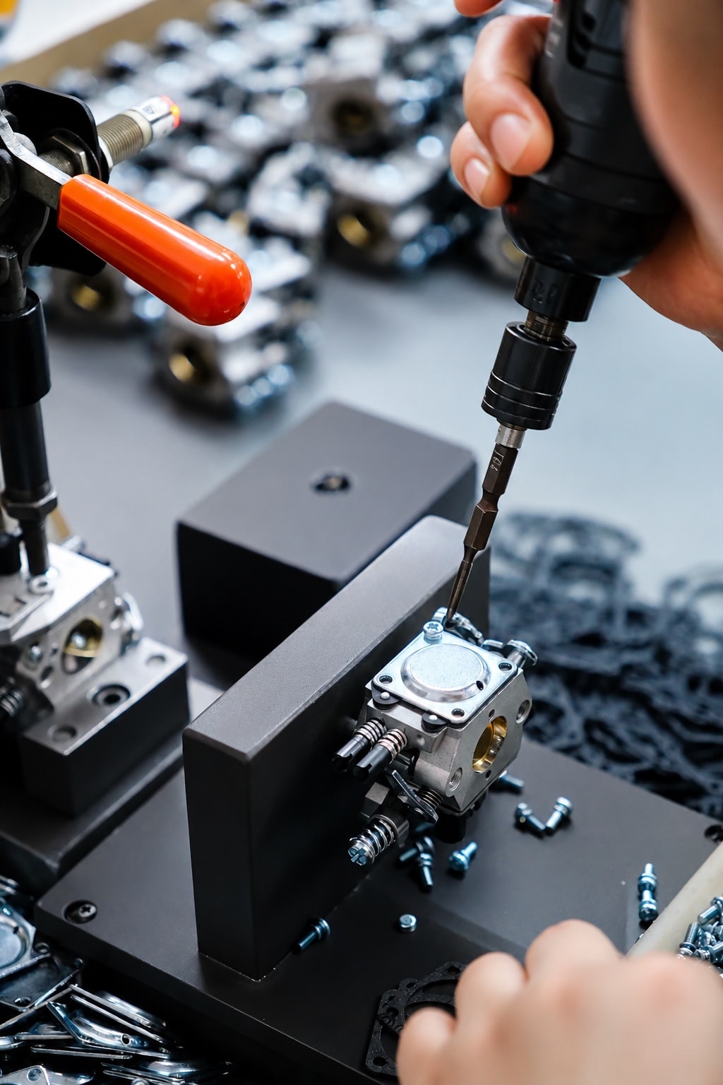
Anodizing, powder coating, sand and shot blasting, vibratory finishing and PVD in-house; bearings, bushes and other components pressed in on request.More →
Choosing the alloy
Compare ADC12, A380, A360 and other grades in the alloy selector.More →
FAQ
Questions we get
Does a billet-machined joint housing need redesigning for die casting?+
Usually a few changes: add draft, even out wall thickness, core out heavy sections, and agree which features the casting holds and which the machining holds. Billet is quicker for design changes during development and small batches; once the design is frozen and volumes rise, a die-cast blank finished by machining usually costs far less per part. We mark up each change at DFM.
Can bearing bores be cast to size? How accurate can they be?+
We would not rely on as-cast bores. The casting carries 0.1–0.3 mm of stock and the bores are finish-bored together with the pilot in one setup on a machining centre. At the level of our production parts that gives φ0.05 mm coaxiality and ±0.02 mm bearing seats, with coaxiality and squareness checked on the CMM.
Will porosity show up after machining?+
The bosses carrying the bores are the heaviest, last-to-freeze sections and the likeliest to hold shrinkage. We squeeze-feed them and keep machining stock thin so the finished faces stay inside the dense skin, with X-ray sampling where it is needed.
What are the MOQ and sampling lead times?+
Samples and pilot runs have no MOQ; production starts at 500 pcs. Before tooling we can supply metal 3D-printed or CNC-machined prototypes, and samples from a simplified or modified tool take 7–15 days; a production tool normally takes 30–45 days to build and T1 trials 3–5 days, and a pilot run can follow sample approval.
FURTHER READING
Technical articles
- TOLERANCES
Die Casting Tolerance vs CNC Machining Tolerance
Understand the difference between die casting and CNC machining tolerances, how tolerance stack-up occurs, and when machining is worth the added cost.
- DEFECTS
Porosity in Die Casting: What Causes It, Why It Matters After Machining, and How Suppliers Control It
Learn why porosity in die-cast parts often becomes visible only after CNC machining, how it causes leaks and rejections, and how experienced suppliers control it.
Note: the parts and figures on this page are representative, based on what we achieve on production parts in the motorcycle, pump and other sectors; we have no published robotics cases yet. Whether a given part can be met is confirmed at drawing review.